 | 1.
Compare Loops (16 Jul 2014)| Charts Comparing Loop Performance. |
| 14281 Visits
17 Images
Gallery Album | |
|
 | 2.
Wi-Fi Folded Dipole - 2400-2500 MHz (5 Nov 2014)Wi-Fi Folded Dipole (2400-2500 MHz) analyzed using 4nec2.
Effect of varying FW (Separation between Folded Dipole Elements) is shown in the
two Parameter Sweep Charts for Narrow and Wider ranges. Gain & SWR are NOT independent of FW. |
| 11744 Visits
7 Images
Shared Album | |
|
 | 3.
UHF Folded & Tri-Folded Dipoles (7 Sep 2011)UHF Folded and Tri-Folded [Bottom Fed] Dipoles analyzed using 4nec2.
UHF Folded Dipole size providing best SWR and Net Gain (470-698 MHz UHF Band):
9.25 x 1.0 inch - Quarter-Inch Copper Tubing (QICT)
9.375 x 1.0 inch - AWG10 Copper Wire |
| 14623 Visits
27 Images
Shared Album | |
|
 | 4.
Hi-VHF+UHF "VEE" Folded Dipole (25 Sept 2014)Hi-VHF+UHF "VEE" Folded Dipole analyzed using 4nec2. Optimized dimensions determined
using nikiml's Python Scripts.
Note that Forward Sweep enhances performance in the UHF Band (third harmonic of Hi-VHF),
although SWR is a bit high for lowest and highest channels.
UHF Raw Gain = 5.1 to 6.7 to 4.8 dBi,
F/B = 8.1 to 2.2 dB and SWR (300-ohms) under 4.8.
Hi-VHF Raw Gain = 1.9 dBi and F/B & F/R = 0.2 to 0.4 and SWR (300-ohms) under 2.2.
Ch2-FM Raw Gain = 0.7 to 1.6 dBi and SWR (300-ohms) 1400-52 is Excessive. |
| 10236 Visits
27 Images
Shared Album | |
|
 | 5.
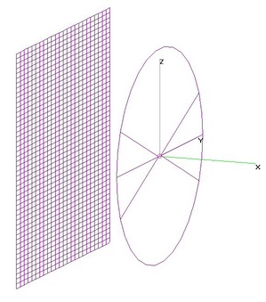
UHF Circular & Square Loops NO Reflector (15 July 2009)UHF Circular & Square Loops analyzed using 4nec2.
a) UHF Circular Loop - NO Reflector:
Ken Nist's Loopa.ez (7.5-in diameter, using AWG12) is a good choice for the Old UHF Band.
A better choice for the (470-698 MHz) UHF Band is 7.75-in diameter, using AWG12.
However, SWR is excessive at lowest and highest frequencies.
SWR can be significantly improved by using QICT (Quarter Inch Copper Tubing), with 8.5-in
Diameter being best size for UHF Band. Raw Gain is then 3.6-5.1 dBi, SWR under 2.7.
b) UHF Square Loop - NO Reflector
Optimum size for UHF Band is 6.9-in per side (x4).
Raw Gain is 3.4-4.1 dBi. SWR is under 2.7. Which is lower Gain than the Circular Loop above.
EDIT (6 Sep 2011): Added UHF Square Loop. |
| 12821 Visits
37 Images
Shared Album | |
|
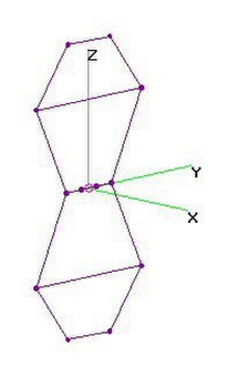
 | 6.
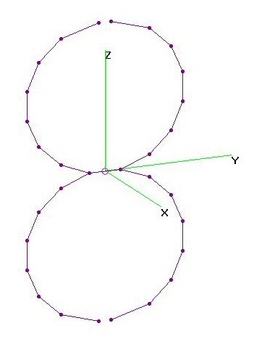
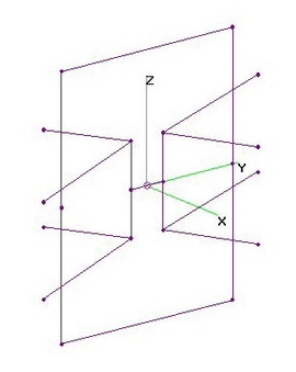
UHF "Figure-8" Twin Loops - NO Refl (6 Sep 2011)UHF "Figure-8" Twin Circular Loops with NO Reflector analyzed using 4nec2.
UHF Raw Gain = 5.6 to 7.4 dBi with SWR (300-ohms) under 2.4 [using QICT].
Should use 9.1-in Diameter, QICT (Quarter-Inch Copper Tubing) or larger for
New [470-698 MHz] UHF Band version (SWR under 2.4, -0.8 dB Mismatch Loss).
AWG10 NOT RECOMMENDED for UHF version, since SWR climbs as high as 3.65 (-1.71 dB Mismatch Loss). |
| 13618 Visits
13 Images
Shared Album | |
|
 | 7.
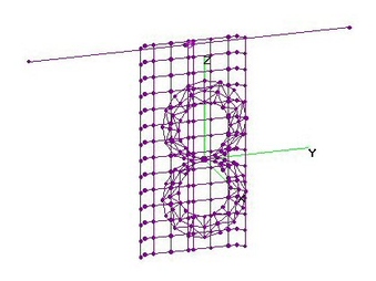
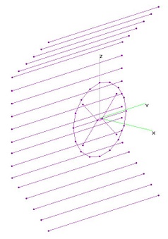
UHF "Figure-8" Twin-Loops + xxRR - OPT (6 Mar 2015)UHF "Figure-8" Twin-Loops + 11 (also 3) Reflector Rods analyzed using 4nec2 after determining
dimensions using nikiml's Python Optimization Scripts.
=====================================
a) Twin-Hoops + 11 Reflector Rods:
UHF Raw Gain = 9.7 to 10.9 dBi, F/B & F/R Ratio Min. = 18.1 dB and SWR (300-ohms) Under 2.2.
Hi-VHF Raw Gain = 5.3 to 6.0 dBi, F/B & F/R = 1.3 to 19.7 dB is Bi-Directional on Lower Channels
and SWR (300-ohms) = 752 to 92 is Excessive.
SUMMARY OF DIMENSIONS (to nearest 1/8-in):
Loop Diameter = 9.125-in,
Reflector Rod Separation behind Hourglass = RS = 4.5-in,
Reflector Rod-to-Rod Separation = RR = 2.125-in,
Reflector Rod Half-Lengths = YRod = 9.875-in.
=====================================
b) Twin-Hoops + 3 Reflector Rods:
UHF Raw Gain = 8.3 to 10.0 dBi, F/B & F/R = 8.9 to 10.2 dB and SWR (300-ohms) Under 1.0.
Hi-VHF Raw Gain = 4.1 to 5.2 dBi, F/B & F/R Ratio = 3.1 to 13.7 dB and SWR (300-ohms) = 673 to 43 is Excessive.
SUMMARY OF DIMENSIONS (to nearest 1/8-in):
Loop Diameter = 9.125-in,
Reflector Rod Separation behind Hourglass = RS = 4.0-in,
Reflector Rod-to-Rod Separation = RR = 4.625-in,
Reflector Rod Half-Lengths = YRod = 11.25-in (are WIDER than 11RR). |
| 9017 Visits
42 Images
Gallery Album | |
|
 | 8.
Hi-VHF Figure-8 Twin Loops - NO Refl (15 July 2009)Hi-VHF "Figure-8" Twin Circular Loops with NO Reflector analyzed using 4nec2.
Optimum size is 24-in Diameter, using QICT (Quarter-Inch Copper Tubing).
Hi-VHF Raw Gain = 5.6 to 6.4 dBi and SWR (300-ohms) Under 2.6. |
| 11023 Visits
5 Images
Shared Album | |
|
 | 9.
UHF Twin-Hoop Chireix - NO or 26ReflRods (18 Aug 2010)UHF Twin-Hoop Chireix with NO or 26 Reflector Rods analyzed using 4nec2.
Used SAME 4nec2 file as Hi-VHF & UHF "Figure-8" Twin Loop, except cut out 1-in Gaps at Top and Bottom of the Hoops.
No doubt due to the much larger size (12.5 vs 9.1-inch), this significantly improved the New UHF Band Gain.
A smaller (10.8-in) diameter would be better for Old UHF Band (up to Ch69).
EDIT (5Sep2011): Added NO Reflector version, optimized for New UHF Band.
UHF Raw Gain = 6.8 to 10.0 dBi and SWR (300-ohms) Under 3.0 (A Bit High). |
| 22420 Visits
30 Images
Shared Album | |
|
 | 10.
Hi-VHF+UHF Tapered Loop - A-D C2 & C2-V (18Jan2015)Hi-VHF and UHF Tapered Loop with Screen Grid Reflector PLUS Hi-VHF Stick Dipole analyzed
using 4nec2, approximating Dimensions for Antennas-Direct C2-V.
DIMENSIONS Per ADTech and user freezer:
Inner Loop Diameter 6-1/4", Outer Loop Diameter 8-5/8" with 1/2" Overlap at Feedpoint.
Gen-I/II VHF Dipole = 37-7/8-in, Reflector = 20-1/8" H x 11-5/8" W x 4-1/16" "Deep".
Feedpoint DETAILS found towards the bottom of fol. webpage:
http://www.hdtvprimer.com/ANTENNAS/TemporaryPage.html
ADTech indicated that there are actually THREE DIFFERENT Generations of the C2-V, using
different VHF Impedance Matching Approaches [NOT analyzed in below results]:
"First and second generation C2Vs used a standard 300/75 ohm matching transformer to match
the dipole to the Holland UVSJ's VHF input. Because of the built-in mismatch, the length
of the dipoles was increased to bring the return loss back down in the center of the VHF band.
Third generation C2Vs that utilize the VHF-1 module utilize a custom PCB matching network
that's closer to a 1:1 ratio, allowing the dipole elements to be shortened by 3.25" inches each
while still having the best return loss at mid-band. The VHF-1 module includes the UVSJ
function internally."
======================================
Four variations were analyzed: UHF C2 with Reflector, Gen-I/II C2-V adding Hi-VHF Dipole, Gen-III/VHF Module
C2-V and C2 without Reflector.
a) C2 Tapered Loop with Screen Grid Reflector:
UHF Raw Gain = 9.6 to 10.1 dBi, F/B & F/R Minimum = 14.9 dB and SWR (300-ohms) Under 1.9.
[A-D C2 Specs: Gain = 9.7 to 10.2, F/B = 20 dB (typ), 22 dB (max at 698 MHz) and SWR (300-ohms) under 3.0.]
======================================
b) Gen-I/II C2-V Tapered Loop, Screen Grid Reflector + Hi-VHF Dipole, connected to UVSJ via 300:75-ohm Balun:
UHF Raw Gain = 9.4 to 10.1 dBi, F/B & F/R Ratio Minimum = 17.9 dB and SWR (300-ohms) Under 2.4.
Hi-VHF Raw Gain = 2.7 to 3.2 dBi, Hi-VHF F/B & F/R Ratio = 0.3 to 0.6 dB and SWR (300-ohms) Under 2.4.
Note the mid-band UHF Loss of about 0.5 dB when adding the VHF Dipole.
Note that despite the VHF Dipole being slightly SHADED by being mounted BEHIND the Reflector,
Hi-VHF Gain was 0.9 to 1.2 dB HIGHER than JUST an Optimized Hi-VHF Dipole [see Link below],
with 0.25 to 0.5 dB MORE in the Forward Direction, so the Reflector must have been acting to
squeeze out more Gain at the expense of Horizontal and Vertical Beamwidths. Also note that
the Side NULLS were limited to about -17 to -15 dBi Gain [A-D calculated -16 to -14 dBi],
rather than forming very deep Nulls more typical of a Dipole without other surrounding Metal:
https://imageevent.com/holl_ands/dipoles/hivhfuhfstickdipolenoreflector
======================================
c) Gen-III/VHF Module C2-V Tapered Loop, Screen Grid Reflector + Hi-VHF Dipole,
combined with UHF Coax via Impedance Matching Network:
T.B.D.
======================================
d) C2 Tapered Loop with Reflector REMOVED, so Bi-Directional:
UHF Raw Gain = 5.5 to 6.8 dBi and SWR (300-ohms) Under 3.2.
Note that INCREASE in Raw Gain is quite significant as the Thickness (Relem) becomes as thin as Aluminum Foil...with INCREASE
to excessive SWR=4.0 at 470 MHz. Al. Foil Relem(STD)=0.000315-in and Relem(HD)=0.00047-in.
However, note that assumed Relem=0.0404 (14-Gauge...or perhaps thinner 16-Gauge) is best match to A-D C2 Specs, esp. SWR.
In below Charts [#52-57], Alum. Foil is on Far Left and AWG-16 on Far Right.
======================================
EDIT (2Apr2015): Uploaded revised charts based on refined dimension information from ADTech.
EDIT (4Dec2016): Added charts showing how Raw Gain INCREASES as the Thickness (Relem) is reduced. |
| 11364 Visits
57 Images
Gallery Album | |
|
 | 11.
Hi-VHF+UHF Tapered DoubleLoop - d510d180 (18Jan2015)Hi-VHF and UHF Tapered Loop with Screen Grid Reflector PLUS Hi-VHF Stick Dipole analyzed
using 4nec2, assuming Loop dimensions per d510d180 post.
Note that 8-in Outer Loop is smaller than 9-in O.D. in Antennas Direct C2-V:
http://www.avsforum.com/forum/25-hdtv-technical/798265-how-build-uhf-antenna-60.html#post15866958
[Code section is missing a Slash??? Had to copy/paste the webpage to MS-Word to extract.]
[Then I had to TRY to fix AGT, but stability issues prevented that...so I rebuilt the entire
Tapered-Loop model, see 4nec2 Files below.]
DIMENSIONS: Size Assembled (per A-D C2 data sheet) = 20" H x 10" W x 5" D (incl. mount?).
Per user d510d180 (presumably based on wavelengths at 470 & 700 MHz) Loop Diameters = 8-in and 5-in.
And Trial Runs revealed best performance with 4-in Separation between Tapered-Loop and Reflector.
Other Dimensions extrapolated from photos, incl. Feedpoint found towards the bottom of fol.:
http://www.hdtvprimer.com/ANTENNAS/TemporaryPage.html
Three variations were analyzed: C2-V with Hi-VHF Dipole, UHF-ONLY C2 with Reflector and C2 without Reflector.
a) Tapered Loop with Screen Grid Reflector PLUS Hi-VHF Dipole:
b) Tapered Loop with Screen Grid Reflector:
c) Tapered Loop without Reflector: |
| 7286 Visits
51 Images
Shared Album | |
|
 | 12.
UHF Shorted Bowtie Loop (SBL) (15 Sept 2009)UHF Shorted Bowtie Loop (SBL) Antenna analyzed using 4nec2.
An SBL is a Loop Antenna with an interior Bowtie acting as a Feedline.
It is compared here to just a Loop as well as just a 6 or 4-Whisker Bowtie. |
| 12619 Visits
12 Images
Shared Album | |
|
 | 13.
Hi-VHF+UHF Bowtie-In-Loop - NO Reflector (20 Apr 2010)Hi-VHF+UHF Bowtie-In-Loop (BIL) Antenna analyzed using 4nec2. Loop Diameter = 23-in, Whiskers = 10-in.
Based on a design (X0512 aka WW_X0498-Rev2,) by WildWillie on www.digitalhome.ca Antenna R&D Forum.
A simple to build antenna with moderate performance in BOTH UHF and Hi-VHF bands.
Design dimensions based on using (about) 1/4-in O.D. Copper Coil. Design would
need to be Re-Optimized for different O.D. so do NOT change to significantly different diameter.
UHF Raw Gain = 4.2-6.6 dBi with SWR (300-ohms) under 1.8 (Excellent).
Hi-VHF Raw Gain more than 3.8 dBi with SWR (300-ohms) under 3.4 (Poor).
Ch2-FM Raw Gain = 1.0 to 2.3 dBi and SWR (300-ohms) = 746 to 77, which is Excessive.
EDIT (25 Sept 2014): Added Ch2-FM Band Performance Charts. |
| 10067 Visits
18 Images
Shared Album | |
|
 | 14.
Hi-VHF+UHF Bowtie-In-Loop + 11RR - OPT (23 Sept 2013)Hi-VHF+UHF Bowtie-in-Loop (BIL) with 11 Reflector Rods analyzed using 4nec2. Dimensions were
determined using nikiml's Python Optimization Scripts. Two separate sets of Reflector Rods with
different Lengths & Separation from BIL were assumed to Optimize Hi-VHF & UHF, using different
Min/Max search ranges.
UHF Min & Max Raw Gain: 8.7 & 10.4 dBi, F/B & F/R Ratio Min = 11.0 dB and SWR (300-ohms) under 3.2.
HiVHF Raw Gain: 7.1 to 6.9 dBi, F/B & F/R Ratio Min = 14.9 dB and SWR (300-ohms) 6.7 to 2.6, which
is excessive on the mid to lower channels but may be acceptable in many situations. |
| 8314 Visits
23 Images
Shared Album | |
|
 | 15.
Hi-VHF+UHF Bowtie-In-Loop (DblAngRefl) (19 Sept 2009)Hi-VHF+UHF Bowtie-In-Loop (BIL) Antenna with 19 Double Angled Reflector Rods analyzed using 4nec2:
X0512 aka WW-X0498-Rev2 design by wildwillie (c), 16Sept2009. Loop Diameter = 23-in, Whiskers = 9-in. |
| 11669 Visits
16 Images
Shared Album | |
|
 | 16.
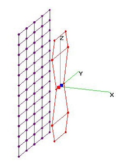
HiVHF+UHF Dreamcatcher (20 Feb 2011)Wildwillie's Hi-VHF+UHF Dreamcatcher (Hourglass) Bowtie-In-Loop variant (X0498-Rev2-Wide) analyzed using 4nec2.
Excellent performance on both Hi-VHF and New UHF TV Bands, with some Gain loss & SWR mismatch
in the Old UHF Band above Ch51.
UHF Raw Gain ~ 6 to 9 dBi and SWR (300-ohms) under 3.0 (Fair).
HiVHF Raw Gain ~ 3.3 to 4.0 dBi and SWR (300-ohms) under 2.3 (Excellent).
Ch2-FM Raw Gain = 2.9 to 2.8 to 3.1 dBi and SWR (300-ohms) = 1226 to 40 is Excessive.
EDIT (25 Sept 2014): Added Ch2-FM Band Performance Charts. |
| 15579 Visits
30 Images
Shared Album | |
|
 | 17.
U+H 2-Bay Hentenna NO+11ReflRods (21 Aug 2011)UHF (+ Hi-VHF) 2-Bay Hentenna with NO Reflector and with 11 Reflector Rods analyzed using 4nec2.
a) UHF 2-Bay Hentenna with NO Reflector:
Analyzed Xauto's version x1052 2-Bay Hentenna: 8.75-in Width x 13-in Height.
Raw Gain = 3.8-5.7 dBi, SWR under 1.8.
b) UHF 2-Bay Hentenna with with 11 Reflector Rods:
dcartier's original 4nec2 file (UHF Gain & SWR Optimized: Score=1.16102) was run for another 30 hours
of optimization (Score=0.660617), using nikiml's Python Scrips, significantly improving F/B & F/R Ratios.
UHF Raw Gain increased about 0.5 dBi. SWR slightly improved from under 2.2 to under 1.8.
F/B and F/R were significantly improved, from a range of 3-7 dB to a range of 7-13 dB.
Hi-VHF Raw Gain was 7.1-5.5 dBi FORWARD and 7.1-8.2 dBi towards the REVERSE.
Unfortunately SWR was very excessive (25-35).
FYI: Temporarily removing GW40 (wire only 0.5-in behind the feedpoint) increases SWR to 4.3.
I've seen this sort of closely coupled "SWR tuning element" technique used in Yagi Antennas,
including the YA-1713:
BTW: I temporarily commented out GW49 & GW50 (small, upper & lower most Reflector Rods)
and reran 4nec2. I was surprised to see that SWR was unchanged, but Gain increased
about 0.5 dBi and F/B & F/R Ratios were slightly improved....so, there may be TOO many
Reflector Rods....go figure....
More (or Fewer?) Reflector Rods may be required to improve the UHF F/R & F/B Ratios...
It is left as an exercise to optimize both UHF and Hi-VHF...preferably, including
both F/R & F/B Ratios explicitly in the "cost function"....longer runs might also help....
EDIT (5Sep2011): Added UHF 2-Bay Hentenna (Square Loop) with NO Reflector. |
| 12333 Visits
30 Images
Shared Album | |
|
 | 18.
UHF Hourglass Loop (30 Nov 2012)UHF Hourglass Loop analyzed using 4nec2 after finding "best" dimensions using nikiml's Optimizations Scripts.
Based on UHF Hourglass Loop posted by oneolddude in www.digitalhome.ca forum.
However Optimization and Rescaling increased 470 MHz Gain by about 0.5 dB with Max Gain on 698 MHz.
Five versions are analyzed here. ALL provide very wide Beamwidths (60-50 degrees even at High Freqs):
#############################################
a) AWG6 or AWG12/10 with NO Reflector Rods (Optimization search across ALL THREE Variables):
UHF Raw Gain = 4.7-6.0 dBi with Excellent SWR under 1.6, using AWG6.
UHF Raw Gain = 5.0-6.0-5.2 dBi with Excellent SWR under 2.0, using AWG12 (or AWG10).
#############################################
b) AWG10 Elements + 1/4" 11x Reflector Rods (Optimization search across ALL THREE Variables):
USB Raw Gain = 9.3 to 10.3 dBi, F/B & F/R Ratio = 19.4 dB and SWR (300-ohms) Under 2.4
#############################################
c) AWG6 Elements + 1/4" 15x Reflector Rods (Search across ALL SIX Variables):
UHF Raw Gain = 9.6 to 10.4 to 10.3 dBi, F/B & F/R Minimum = 19.6 dB and SWR (300-ohms) Under 1.8.
#############################################
d) AWG12 Elements + AWG12 15xReflector Rods:
UHF Raw Gain = 9.4 to 10.2 dBi, F/B & F/R Minimum = 17.1 dB and SWR (300-ohms) Under 1.8.
#############################################
e) Grid Mesh 24x19.5-in (per 300-ohm post):
UHF Raw Gain = 9.4-10.8 dBi with SWR under 2.4, using AWG6.
Front/Back and Front/Rear Ratios 15 dB or better.
#############################################
f) Grid Mesh 24x19.5-in (Re-Optimized using nikiml's Python scripts):
UHF Raw Gain = 9.5-10.6 dBi with SWR under 2.5, using AWG6.
Front/Back and Front/Rear Ratios 17 dB or better.
PS: For improved F/B and F/R Ratios, should try different Grid Mesh sizes.
EDIT (10Dec2012): Added 4nec2 analysis with Grid Mesh (per 300ohm post) and
Re-Optimized version, with somewhat better F/B and F/R Ratios.
EDIT (10Jul2014): Replaced 15xRR version with improved SWR version (with 0.2 drop in Gain).
EDIT (8Mar2015): Added 11RR version. |
| 13906 Visits
81 Images
Gallery Album | |
|
 | 19.
UHF Quad-Trapezoid-Loop (11 Jul 2014)UHF Quad-Trapezoid-Loop Antenna analyzed using 4nec2, formed by adding outer parts
of Chireix 2-Square to an Hourglass-Loop. All dimensions determined using nikiml's
Optimization Scripts.
Three versions analyzed: Quad-Trap (NO Reflector), Quad-Trap (11 RR) and Quad-Trap (15 RR).
=================================================
a) Quad-Trapezoid-Loop (NO Refl): AWG10 Elements.
UHF Raw Gain = 6.7 to 8.4 to 7.8 dBi and SWR (300-ohms) under 1.8.
Note Very Wide 70-60 degree Beamwidth.
=================================================
b) Quad-Trapezoid-Loop + 11 Reflector Rods: AWG10 Elements and 1/4-in O.D. Reflector Rods.
UHF Raw Gain = 9.7 to 11.6 dBi, F/B & F/R Ratio Min. = 19.9 dB and SWR (300-ohms) Under 1.9.
BEAMWIDTH is 60 to 50 degrees across UHF Band with a VERY DEEP Notch directly to the Rear.
=================================================
c) Quad-Trapezoid-Loop + 15 Reflector Rods: AWG10 Elements and 1/4-in O.D. Reflector Rods.
UHF Raw Gain = 10.1 to 11.8 dBi, F/B & F/R Ratio Min =19.2 dB and SWR (300-ohms) under 2.7.
Note VERY WIDE BEAMWIDTH, 60-degrees ALL across the UHF Band and the VERY DEEP
Notch directly to the Rear.
EDIT (7Mar2015): Added 11RR version. |
| 13984 Visits
51 Images
Gallery Album | |
|
 | 20.
UHF Quad-Trapezoid-Loop+2xBars (11 Jul 2014)UHF Quad-Trapezoid-Loop + 2 Bar Elements analyzed using 4nec2.
Formed by adding outer parts of Chireix 2-Square Antenna to an Hourglass-Loop.
All dimensions determined using nikiml's Optimization Scripts. Picture posted by schoolbus:
http://www.digitalhome.ca/forum/186-antenna-research-development/157816-urban-commando-uhf-loop-substitution-6.html#post2287090
Two versions analyzed: Quad-Trap+2xBars (NO Reflector) and Quad-Trap+2xBars (15 RR).
=================================================
a) Quad-Trapezoid-Loop+2xBars (NO Refl): AWG10 Elements.
UHF Raw Gain = 6.6 to 9.4 dBi, SWR (300-ohms) under 1.8 and Beamwidth = 80 to 50-degrees.
=================================================
b) Quad-Trapezoid-Loop+2xBars + 11 Reflector Rods: AWG10 Elements and 1/4-in O.D. Reflector Rods.
UHF Raw Gain = 11.2 to 12.6 to 11.5 dBi, F/B & F/R Ratio Min. = 17.8 dB and SWR (300-ohms) Under 2.8.
Beamwidth = 60 to 50 degrees.
Hi-VHF Raw Gain FWD = -1.9 to -6.9 to 0.6 dBi and Hi-VHF Raw Gain TO REAR = 6.0 to 1.2 dBi with
F/B & F/R Ratio = 7.9 to 12.7 to 0.6 dB and SWR (300-ohms) = 40 to 2.8.
=================================================
c) Quad-Trapezoid-Loop+2xBars + 15 Reflector Rods: AWG10 Elements and 1/4-in O.D. Reflector Rods.
UHF Raw Gain = 11.4 to 12.6 to 11.1 dBi, F/B & F/R Ratio Min = 18.1 dB and SWR (300-ohms) under 2.5.
Note 60-50 degree Beamwidth and EXTREMELY DEEP 64+ dB Notch directly to Rear. |
| 14728 Visits
51 Images
Gallery Album | |
|
 | 21.
UHF Quadazoid Loop - No Refl (23 Mar 2018)UHF Quadazoid Loop (No Reflector) analyzed using 4nec2 after determining "best"
Dimensions using nikiml's Python Optimizer Scripts. ["Quadazoid" = Quadruple Trapezoid.]
UHF Raw Gain = 6.3 to 7.4 to 6.2 dBi and SWR (300-ohms) Under 1.7.
UHF Beamwidth = 82 to 72 degrees, Bi-Directional, decreasing with Freq. |
| 1511 Visits
21 Images
Shared Album | |
|
 | 22.
UHF Quadazoid Loop + Reflector (23 Mar 2018)UHF Quadazoid Loop with Reflector analyzed using 4nec2 after determining "best"
Dimensions using nikiml's Python Optimizer Scripts.
Note that OPTimized Dimensions WITH Reflector are somewhat DIFFERENT than without.
Two different Reflector Types were analyzed:
#######################################
a) Screen Grid Reflector = 24"H x 16"W with Grid = 2"H x 4"W.
UHF Raw Gain = 9.8 to 10.4 to 9.8 dBi, F/B & F/R Gain Min. = 14.1 dB
and SWR (300-ohms) Under 1.3...with Beamwidth = 71 to 67-deg, decreasing with Freq.
So performance is very comparable to A-D C2.
#######################################
b) 11 Reflector Rods:
UHF Raw Gain = 10.0 to 11.0 to 10.2 dBi, F/B & F/R Gain Min. = 18.0 dB
and SWR (300-ohms) Under 2.2...with Beamwidth = 66 to 56-deg, decreasing with Freq..
Higher Gain is likely due to significantly Wider Reflector. |
| 1696 Visits
42 Images
Shared Album | |
|
 | 23.
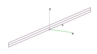
Hi-VHF Folded Dipoles (15 July 2009)Hi-VHF Folded Dipoles with wide variance in element sizes analyzed using 4nec2.
Example 4nec2 files included for most antennas.
Here's an on-line Folded Dipole Calculator:
http://www.k7mem.150m.com/Electronic_Notebook/antennas/folded_dipole.html
Note that IF element diameters are the same, impedance does not change as you vary the separation.
By adding a Reflector and a Director, you've got a simple 3-Element YAGI:
http://www.wfu.edu/~matthews/misc/dipole.html
Some DIY Folded Dipole examples:
oldsyd's (new) Ch7: http://img4.imageshack.us/img4/6002/foldeddipole1.jpg
oldsyd's (old) Ch7: http://img23.imageshack.us/img23/180/0000241.jpg
mlord's Ch6: http://www.digitalhome.ca/forum/showthread.php?p=833571
There is a Quasi-optimum Separation between Folded Dipole Elements of about two inches for larger diameters,
one inch for moderate and 1.0 to 0.5 inch for small wires. But a 2:1 variation causes only small differences in SWR.
Hi-VHF sizes providing best SWR and Net Gain (centered on CH9/10) are:
27.0 x 2.0 inch - One Inch Diameter Copper Tubing
27.5 x 2.0 inch - 1/2-in Copper Tubing (Type M)
28.0 x 1.5 inch - 5/16-in O.D. Copper Tubing (not much better than quarter inch)
28.0 x 1.0 inch - Quarter Inch O.D. Copper Tubing (or RG-58/59 Braid Shield Coax)
28.25 x 0.75 inch - AWG12 Copper Wire (may leave insulation on in VHF band)
24.50 x 0.5 inch - AWG24 Copper Wire (may leave insulation on)
[ALL MEASUREMENTS ARE CENTER-TO-CENTER.]
Sizes may be rescaled by same fraction as frequencies change, using LONGER elements for LOWER frequencies.
For example, minimum SWR for AWG12 occurs at 192 MHz (between Ch9&10). To move minimum SWR to 207 MHz (Ch12),
shorten 28.25-in by fraction 192/207 or 26.2-in. Separation between Folded Dipole Elements won't make much difference.
QtrInchCopper Tubing, 1/2-in Type M Copper Tubing and 1-in O.D. provide good SWR across entire Hi-VHF band.
AWG12 and AWG24 are best ONLY over 2 adjacent channels (Ch9-10 example shown).
Total parts cost: about $10 for 10-ft piece of 1/2-in Type M Copper Tubing, 4 Copper Elbows, 2 Caps and a cheap Balun.
FYI: johnrmckee measured 0.5 dB VHF/UHF loss for Philips Outdoor Balun:
http://www.avsforum.com/avs-vb/showthread.php?p=15851345
This is consistent to what I've measured for Radio Shack, RCA and Channel Master Baluns at VHF.
But Philips Outdoor Balun is first one I've seen with low loss across the UHF Band.
So after finishing these NEC Sim runs, I was Googling around for some additional Folded Dipole examples:
Yup, it's 1/2-in Copper Pipe with 4 Elbows: http://pigtail.net/nicholas/ctn/dipole.html
EDIT (22Jun2009): Added photos of DIY construction for a Hi-VHF Folded Dipole using 1/2-in Copper Pipe.
Since he actually had (one and only one) experience brazing a pipe joint....and the tools...my son did this job.
Last week he had to replace a corroded valve on his water heater....making him an expert compared to me....
EDIT (28Jun2009): Hung Hi-VHF Folded Dipole (1/2-in Pipe version) at 7-ft height on Outdoor Pergola 70-miles SE fm Mt Wilson (L.A.).
Ch7/9 very watchable but weak (80-90% QUALITY on Dish vip622 DVR with 65-70% "SIGNAL STRENGTH").
Did not expect Ch11/13 due to Ch12 being only 2.7 miles away and Folded Dipole doesn't have sharp null in requisite direction.
EDIT (3Sep2011): Used 4nec2 to analyze different Feedpoint Gap sizes in a Folded Dipole (L=27.5, OD=0.569-in Cu).
Raw Gain and Net Gain were within 0.1 dB, whether 0.75, 1.0 or 1.45-in, so Gap Size in Unimportant.
BTW: 1.45-in is the Source segment size in the posted 4nec2 file with one continuous driven element. It was not possible
to test 0.5-in Gap size, due to 4nec2 declaring errors due to it's small size, not fixable with different AutoSeg( ) choices.
EDIT (22Nov2012): Moved Ch6 and Vertical FM Charts to new Lo-VHF Folded Dipole album. |
| 31692 Visits
41 Images
Shared Album | |
|
 | 24.
Hi-VHF Circular Loop + Reflector (15 July 2009)Hi-VHF Circular Loop with either Loop or Screen Reflector analyzed using 4nec2.
a) With Loop Reflector, Net Gain was 8 dBi on Ch7, dropping to 6 dBi on Ch13 with excellent SWR, except for small increase on Ch7.
Adding Loop Reflector increased Net Gain by 2-4 dB (less at high freqs) with more than 8.7 dB F/B (and F/R) using
Optimum Diameter=22-in for Half-Inch Copper Tubing. Best F/B (and F/R) is on Ch8-10.
Optimum Diameter=21.5-in for Quarter Inch Copper Tubing (QICT) was nearly as good, with more than 7.3 dB F/B (and F/R).
Smaller Circular Loop Element sizes not analyzed since a Square Loop (Quagi) would be easier to construct.
Loop Reflector dimensions are optimized for full Hi-VHF Band coverage.
Rescaling to optimize Ch7 will have only minor-moderate impact to Ch13 F/B, F/R and SWR.
However, rescaling to optimize Ch11-13 will degrade F/B, F/R and especially SWR on CH7-10.
b) EDIT (16 Sep 2009): Added analysis of alternative Hi-VHF Circular Loop with Minimalist 28" H x 34" W Screen Reflector:
Hi-VHF Raw Gain = 7.9 dBi, F/B & F/R Ratio = 11.5 to 15.2 dB and SWR (300-ohms) Under 3.2.
c) EDIT (5 Oct 2013): Added analysis of alternative Hi-VHF Loop with 40" H x40" W Screen Reflector to improve F/B & F/R Ratios:
Hi-VHF Raw Gain = 8.2 to 8.3 dBi, F/B & F/R Ratio = 13.7 to 15.5 dB and SWR (300-ohms) Under 2.7.
d) EDIT (15 Jul 2014): Added Circular Polarization analysis of alternative Hi-VHF Loop with 28" H x 34" W Screen Reflector. |
| 11783 Visits
43 Images
Gallery Album | |
|
 | 25.
Hi-VHF Square Loop + Reflector (19 Aug 2011)Hi-VHF Square Loop [20"/side] with 28"x28" Screen Reflector (2"x4" Grid) at 13" Separation and 1/2-in Type M Copper analyzed using 4nec2.
Raw Gain = 7.6-7.9 dBi, F/B and F/R Ratio = 6.0 to 13 dB and SWR under 3.0. |
| 11806 Visits
9 Images
Shared Album | |
|
 | 26.
HiVHF Shorted Bowtie Loop (NO Reflector) (18 Sept 2009)Hi-VHF Shorted Bowtie Loop (46-in Diameter using Half-Inch Copper Tubing) analyzed using 4nec2.
Optimized for Hi-VHF Band (Ch7-13) but also provides minimal performance on Ch6 & FM Band.
CH2-5 also have 2.6-3.0 dBi of Raw Gain, but SWR becomes excessive on lowest channels. |
| 7772 Visits
17 Images
Shared Album | |
|
 | 27.
Hi-VHF Shorted Bowtie Loop (w Reflector) (18 Sept 2009)Hi-VHF Shorted Bowtie Loop with Reflector) analyzed using 4nec2.
Optimum Loop Diameter = 44-in with Half-Inch-Copper-Tubing for 48-in H x 48-in W Screen Reflector (1"x2" Grid).
This minimum Screen size was determined by size of typically available fencing material.
Angled Reflectors beyond the 48x48 Grid may be added to improve Gain by reducing Horiz. and/or Vert. Azimuthal coverage.
Optimum Diameter for smaller Element sizes may be slightly different.
Hi-VHF Raw Gain = 8.2 to 8.4 dBi, F/B & F/R Ratio = 14.4 to 13.0 dB and SWR (300-ohms) Under 2.5. |
| 7773 Visits
9 Images
Shared Album | |
|
 | 28.
Hi-VHF Hourglass Loop (30 Nov 2012)Hi-VHF Hourglass Loop analyzed using 4nec2 after finding "best" dimensions using nikiml's Optimization
Scripts. Based on UHF Hourglass Loop posted by oneolddude in www.digitalhome.ca forum:
1/4-in O.D. Elements and Reflector Rods.
NO Reflector Rods (Optimized H=41.75-in, W=34.5-in & Feedpoint Gap=2.5-in):
Ch7-13 Raw Gain = 5.3-6.1 with Excellent SWR under 1.6 (using Quarter-inch Copper Tubing).
Provides about 4 dBi Raw Gain on Ch2-6 and FM Band, but SWR is excessive.
Also provides some Raw Gain with acceptable SWR in UHF Band, but only over mid-band frequencies.
Charts assume Quarter-Inch-Copper, e.g. Tubing or RG-59 braid shield (no need to strip insulation).
Much smaller size AWG12 wire has NO effect on Gain and only increases SWR to 2.0,
so feel free to use even smaller wire sizes.
Add 15 Reflector Rods (Optimized Width, Rod-Rod Separation & Separation from Hourglass):
Ch7-13 Raw Gain = 9.7-10.05 dBi with SWR under 3.1 (using Quarter-inch Copper Tubing).
Reflector Total Height = 68-in x Width = 56.5-in.
Excellent Front/Rear (hemisphere) Ratio = 32-34 dB with Front/Back (toward 270-deg) = 20 dB.
Provides some Raw Gain on Ch2-6 and FM Band, but directed to the REAR and SWR is excessive.
Not suitable for UHF Band: poor SWR & Gain toward Diagonals.
With 15-RR, provides Gain nearly as much as Winegard YA-1713, except sidelobe nulls moved
to sides and consistently EXCELLENT F/B and F/R Ratios.
EDIT (4Jun2013): Added Hourglass with 11 Reflector Rods and with 7 Reflector Rods to illustrate
how much reduction to expect in Gain and F/R Ratio. Also note that Reflector Height and Width are
significantly smaller.
EDIT (6Jun2013): Added Comparison Chart showing improvement in Raw Gain & F/R Ratio with more RRs.
EDIT (14Dec2014): Added 5RR and 3RR versions with provided 70-deg Beamwidth across entire Hi-VHF Band.
Note that 5RR version had better, flatter Raw Gain curve. |
| 95520 Visits
70 Images
Gallery Album | |
|
 | 29.
Hi-VHF Quad-Trapezoid-Loop (5 Jul 2016)Hi-VHF Quad-Trapezoid-Loop Antenna analyzed using 4nec2, formed by adding outer parts
of Chireix 2-Square to an Hourglass-Loop. All dimensions determined using nikiml's
Optimization Scripts.
Hi-VHF Raw Gain = 7.3 to 8.7 dBi and SWR (300-ohms) Under 1.6. |
| 5896 Visits
14 Images
Shared Album | |
|
 | 30.
Hi-VHF Quad-Trapezoid-Loop+2Bars - OPT (7 Jul 2016)Hi-VHF Quad-Trapezoid-Loop+2Bars Antenna analyzed using 4nec2, formed by adding outer parts
of Chireix 2-Square to an Hourglass-Loop and then adding two Horizontal Elements attached to the Balun Feedpoint.
All dimensions determined using nikiml's Optimization Scripts, assuming AWG10 Wire Size
(which is NOT all that critical).
Hi-VHF Raw Gain = 8.8 to 9.6 to 8.8 dBi and SWR (300-ohms) Under 1.7. |
| 5541 Visits
15 Images
Shared Album | |
|
 | 31.
Lo-VHF Tri-Folded Dipoles - OPT (9 May 2018)Lo-VHF Tri-Folded Dipoles analyzed using 4nec2.
FYI: Ch6 Center Freq = 85 MHz so 1/2-WL = 69.43-in.
#####################################
a) Ch6 Tri-Folded [Bottom Fed] Dipole with "best" Dimensions for 600-ohm Load
determined using nikiml's Python Optimization Scrips, presuming AWG10
[for a typical indoor/attic location]:
L2=65.59-in = Folded Dipole Overall Element Length.
Ch6 (82-88 MHz) Raw Gain = 2.1 to 2.2 dBi and SWR (600-ohms) = 1.2 to 1.6.
SWR (300-ohms) = 1.7 to 1.2 to 2.6 is also Acceptable...[and can reduce if add Reflector].
#####################################
b) Ch6 Tri-Folded [Bottom Fed] Dipole with "best" Dimensions for 300-ohm Load
determined using nikiml's Python Optimization Scrips, presuming AWG10
[for a typical indoor/attic location]:
L2=63.61-in = Folded Dipole Overall Element Length.
Ch6 (82-88 MHz) Raw Gain = 2.1 to 2.2 dBi and SWR (300-ohms) = 1.9 to 1.7 to 2.0.
#####################################
d) Ch6 Tri-Folded [Center Fed] Dipole with "best" Dimensions determined using
nikiml's Python Optimization Scrips, presuming AWG10 for an indoor/attic location:
L2=62.23-in = Folded Dipole Overall Element Length.
Ch6 (82-88 MHz) Raw Gain = 2.1 to 2.2 dBi and SWR (1200-ohms) = 1.2 to 1.4.
. |
| 1519 Visits
43 Images
Shared Album | |
|
 | 32.
Lo-VHF 2-Bay Folded Dipole - OPT (9 May 2018)Lo-VHF 2-Bay Folded Dipoles analyzed using 4nec2.
FYI: Ch6 Center Freq = 85 MHz so 1/2-WL = 69.43-in.
######################################
a) Ch6 2-Bay Folded Dipole [using AWG10] with "best" Dimensions determined using
nikiml's Python Optimization Scripts:
L2 = 65.21-in = Folded Dipole Overall Element Length [OPTimized]
HS = 84.11-in = Height Separation between Folded Dipoles [OPTimized, Max=100-in]
FS = 1.01-in = Feedline Separation [OPTimized]
Gap = Gap Size = FS [CROSS-BAR CONSTRAINT]
FW = 2-in = Separation between FD Elements [CONSTRAINT]
RACT = Rfeed = 0.051 [All AWG10]
Ch6 (82-88 MHz) Raw Gain = 6.4 to 6.6 to 6.4 dBi and SWR (300-ohms) = 1.8 to 1.6 to 2.1.
######################################
b) Same, except Half-Wavelength Dimensions, i.e. L2+FW = HS = 1/2-WL = 69.43-in.
Somewhat lower Gain, SWR still Excellent.
Ch6 (82-88 MHz) Raw Gain = 5.9 to 6.3 dBi and SWR (300-ohms) = 2.0 to 1.6 to 2.0. |
| 1487 Visits
14 Images
Shared Album | |
|
 | 33.
VHF Square & Circular Loops (16 July 2009)VHF Square and Circular Loops are analyzed using 4nec2 to find optimum sizes.
Optimum size for Hi-VHF Square Loop is 20-inches per side (Center-to-Center)
for 1/2-in (Type M) Copper pipe (OD=0.569-in),
18.5-inches for 1/4-in Copper Tubing and 16.75-inches for AWG24 wire, which
would be less visible in a window.
Hi-VHF Square and Circular Loops are analyzed using 4nec2 to find optimum sizes.
Optimum size for Hi-VHF Circular Loop is 24-inches Diameter (Center-Center) using
"3/8-in" Copper Tubing (actual OD=0.514-in). Despite smaller diameter,
Circular Loop had slightly higher Raw and Net Gain than Square Loop.
Optimum size for Hi-VHF Circular Loop using QICT (QuarterInchCopperTubing) is 23-in,
AWG12 is 21.5-in and AWG26 is 21-inches (very thin to invisibly tape to a window).
A 10-ft length of 1/2-in Copper Pipe and four 90-deg Elbows costs about $10.
"3/8-in I.D." Copper Coil for Circular Loop is even less.
=================================
Lo-VHF Circular and Square Loop Optimum Dimensions:
[AWG12 typ. for Indoors and HICT = Half-Inch Copper Tubing...or LARGER for Outdoors.]
Circular Loop Diameters:
Ch6 = 48.0-in [AWG12], Raw Gain = 3.6 to 3.8 dBi, SWR Under 2.5.
Ch3 = 64.5-in [AWG12], Raw Gain = 3.5 to 3.9 dBi, SWR Under 2.4
Ch3+4 = 64.5-in [HICT], Ch3 Raw Gain = 3.5 to 3.9 dBi, SWR Under 2.4.
Square Loop Lengths per Side:
Ch6 = 38.0-in [AWG12], Raw Gain = 3.3 to 3.5 dBi, SWR Under 2.5.
Ch3 = 51.0-in [AWG12], Raw Gain = 3.2 to 3.5 dBi, SWR Under 2.7.
Ch2 = 56.5-in [AWG12], Raw Gain is about 3.3 dBi, SWR Under 2.7.
Ch3+4 = 52.0-in [HICT], Ch3 Raw Gain = 3.3 to 3.6 dBi, SWR Under 2.7.
=================================
EDIT (16Jul2009): Analyzed additional element sizes for Hi-VHF Circular Loop.
EDIT (11Jun2013): Added Ch2 Square Loop analysis with Optimum Dimensions.
EDIT (4Jan2015): Added Circular Polarization Response Charts for 23-in QICT Circular Loop.
EDIT (28Mar2017): Added Optimized Circular and Square Loop Charts for
AWG12 (Indoors) and HICT (Outdoor). |
| 25484 Visits
60 Images
Shared Album | |
|
 | 34.
Lo-VHF Folded Dipoles (22 Nov 2012)VHF Folded Dipoles, including specifically for Ch2-6, Ch2-FM, only Ch6 and only FM, analyzed using 4nec2.
Includes Omnidirectional Vertical Dipole for FM Band, but see OMNIDIRECTIONAL album for more info.
Example 4nec2 files included for most antennas.
Some DIY Folded Dipole examples:
oldsyd's (new) Ch7: http://img4.imageshack.us/img4/6002/foldeddipole1.jpg
oldsyd's (old) Ch7: http://img23.imageshack.us/img23/180/0000241.jpg
mlord's Ch6: http://www.digitalhome.ca/forum/showthread.php?p=833571
Note that even HICT (Half-Inch Copper Tubing) is NOT FAT ENOUGH to provide "acceptable" SWR
[i.e. Under 2.7 so Mis-match Loss under 1.0 dB] for ENTIRE Lo-VHF Band (Ch2-6), but is
just slightly over SWR = 2.7 for Ch3-6. And small, AWG24 wire size [such as is used
in 300-ohm Twin-lead] was only suitable for SINGLE CHANNEL Antennas.
There is a Quasi-Optimum Separation between Folded Dipole Elements of about two inches for larger diameters,
one inch for moderate and 1.0 to 0.5 inch for small wires. But a 2:1 variation causes only small differences in SWR.
Optimized Folded Dipole sizes are:
63.0 x 2.0 inch - 0.569-in (Type M) Copper Tubing (Ch6, also OK for CH5 and FM Band)
63.4 x 2.0 inch - 0.25-in O.D. Copper Wire (Ch6, but SWR high for CH5 & FM Band).
64.0 x 2.0 inch - AWG10 Copper Wire (Ch6, but SWR too high for CH5 & FM Band).
64.0 x 3.0 inch - AWG12 Copper Wire (Ch6, but SWR too high for CH5 & FM Band).
65.5 x 0.5 inch - AWG12 Copper Wire (Ch6, but SWR too high for CH5 & FM Band).
66.2 x 0.5 inch - AWG24 Copper Wire (Ch6, but SWR too high for CH5 & FM Band).
[Reduce length by velocity factor if using 1/2-in Twinlead.]
76.0 x 2.5 inch - 0.569-in (Type M) Copper Tubing (Ch3-6, although SWR high on Ch3 & Ch6)
82.0 x 2.5 inch - 0.569-in (Type M) Copper Tubing (Ch2-6, although SWR high on Ch2 & Ch6)
99.24 x 0.5 inch - AWG24 Copper Wire (Ch2 ONLY) [Reduce Length by Velocity Factor if using 1/2-inch Twinlead.]
Optimum size for an almost OMNIDIRECTIONAL VERTICAL Folded Dipole for just the FM Band is 53.0 x 8.0 inch
using 0.569-in O.D. Copper Tubing. Gain away from feedpoint is 2.6 dBi and 1.4 dBi in opposite direction.
A clamp can be attached to the center of the long element since it is at zero ground potential.
Alternative size for Horizontal or Vertical FM Folded Dipole is 55-in x 4-in. Both use Feedpoint Gap=1.25-in.
Folded Dipoles for FM Band frequently come with a Receiver: http://kgnu.org/ht/helpfm.html
Here's an on-line Folded Dipole Calculator:
http://www.k7mem.com/Electronic_Notebook/antennas/folded_dipole.html
Note that IF element diameters are the same, impedance does not change as you vary the separation.
By adding a Reflector and a Director, you've got a simple 3-Element YAGI:
http://www.wfu.edu/~matthews/misc/dipole.html
EDIT (22Nov2012): Moved Ch6 and Vertical FM Charts to this new Album from Hi-VHF Folded Dipole album.
Added analysis of optimized sizes for Ch2-6 and Ch3-6 Folded Dipoles.
EDIT (13Jun2013): Added Ch2 (ONLY) Folded Dipole using AWG24 (e.g. 1/2-in Twinlead).
EDIT (9May2018): Added Ch6 (ONLY) Folded Dipole using AWG10 and QICT. |
| 14649 Visits
38 Images
Shared Album | |
|
 | 35.
LoVHF Hourglass-Loop - No Reflector (15 Oct 2013)Ch3-6 Optimized Hourglass-Loop Antenna (with NO Reflectors) analyzed using 4nec2,
with somewhat higher SWR on Ch2 and FM Band.
NO REFLECTOR RODS:
Ch3-6 Raw Gain = 3.8 to 5.4 dBi and SWR Under 2.7.
Wire Size is NOT critical for Hourglass-Loop. Charts presume AWG8, but there is
very little change between using AWG12 or 1/2-in Copper Tube.
A CONSTRAINT was imposed to limit the HEIGHT of the Antennas to 84-inches (7-feet) MAX. |
| 12425 Visits
8 Images
Shared Album | |
|
 | 36.
LoVHF+FM Hourglass Loop (29 Nov 2012)Ch2-6 + FM Hourglass Loop analyzed using 4nec2 after finding "best" dimensions using nikiml's Optimization Scripts.
Based on UHF Hourglass Loop posted by oneolddude in www.digitalhome.ca forum.
Cut a 1-in wide hole in the middle of the 15-in long "Feedpoint Gap" to attach 300:75-ohm Balun Transformer.
Although the below results presumed 0.569-in O.D. Copper Tubing/Pipe, the design is not that
sensitive to wire size. AWG10 (House Wire) loses 1 dB Raw Gain, with SWR under 2.2.
NO Reflector Rods (Overall 67.5-in H x 87.25-in W, using Half-inch Copper Tubing):
Raw Gain = 3.3-4.5 dBi on Ch2-6, rising to 5.5 dBi across FM Band.
Gain Loss across Ch8-13 is due to Azimuth moving to diagonals.
Excellent SWR on all channels.
CONSTRUCTION HINT:
I would use 3/4-in PVC tubes (white sprinkler or grey PVC electrical conduit if Outdoors) in a
Rectangle a bit bigger than Antenna, held together with 90-deg Elbows PLUS 4 Tie Wraps through holes.
For rigidity, I would add TWO more horizontal cross pieces at about 1/3 and 2/3 height levels.
PVC Glue should be used ONLY on the Elbows and TEE's where they connect to the HORIZONTAL pieces,
with NO GLUE on the Vertical pieces to facilitate assembly on the Ground and partial disassembly
into a tight bundle that can be feed up through an Attic Entry Hole. Glue MAY NOT be needed once
re-assembled in the Attic....or perhaps use small globs of RTV that can be cut if need be. |
| 9680 Visits
18 Images
Shared Album | |
|
 | 37.
LoVHF Hourglass-Loop + 3 ReflRods (19Jul2013)Ch2, Ch3 and Ch6 Hourglass-Loops with Multiple Reflector Rods analyzed using 4nec2 after
Optimization using nikiml's Python Scripts.
For best performance on OTHER than Ch2, multiply Dimensions by Rescale Factor F = 57 / (Rescaled Freq).
For best performance on OTHER than Ch6, multiply Dimensions by Rescale Factor F = 85 / (Rescaled Freq).
a) Ch2 AWG10 Hourglass-Loop with 3 Reflector Rods.
On Ch2, Raw Gain = 9.7 to 9.0 dBi, F/B & F/R Ratio Minimum = 11.8 dB and SWR Under 2.7.
Total Hourglass Height=150.0-in, Width=91.25-in & Mid Gap=1.0-in.
Reflector Rod Lengths=108.5-in with Rod-Rod Spacings=70.0-in and RR-Bowtie Separation=42.25-in.
b) Ch2 AWG10 Hourglass-Loop with 3 Reflector Rods, Max Height = 8-feet ("SHORT").
On Ch2, Raw Gain = 8.4 to 7.8 dBi, F/B & F/R Ratio Minimum = 14.5 dB and SWR Under 2.3.
Total Hourglass Height=96.0-in, Width=96.0-in (Overly Constrained?) & Mid Gap=1.0-in.
Reflector Rod Lengths=96.0-in (Overly Constrained?) with Rod-Rod Spacings=48.0-in
(Overly Constrained?) and RR-Bowtie Separation=37.25-in. [Need To Rerun.]
c) Ch3 AWG10 Hourglass-Loop with 3 Reflector Rods.
On Ch3, Raw Gain = 9.9 to 9.2 dBi, F/B & F/R Ratio Minimum = 11.8 dB and SWR Under 2.8.
Total Hourglass Height=143.5-in, Width=82.0-in & Mid Gap=1.0-in.
Reflector Rod Lengths=97.25-in with Rod-Rod Spacings=69.25-in and RR-Bowtie Separation=38.25-in.
d) Ch3 AWG10 Hourglass-Loop with 3 Reflector Rods, Max Height = 8-feet ("SHORT").
On Ch3, Raw Gain = 8.7 to 8.1 dBi, F/B & F/R Ratio Minimum = 14.5 dB and SWR (300-ohms) Under 2.0.
Total Hourglass Height=96.0-in, Width=89.0-in & Mid Gap=1.0-in.
Reflector Rod Lengths=100.5-in with Rod-Rod Spacings=48.0-in and RR-Bowtie Separation=34.375-in.
e) Ch6 AWG10 Hourglass-Loop with 3 Reflector Rods, Max Height = 10-feet. [T.B.D.]
f) Ch6 AWG10 Hourglass-Loop with 3 Reflector Rods, Max Height = 7-feet ("SHORT").
On Ch6, Raw Gain = 9.2 to 8.8 dBi, F/B & F/R Ratio Minimum = 15.0 dB and SWR (300-ohms) Under 2.0.
Total Hourglass Height=84.0-in, Width=62.9-in & Mid Gap=1.0-in.
Reflector Rod Lengths=72.8-in with Rod-Rod Spacings=42.0-in and RR-Bowtie Separation=26.875-in. |
| 9573 Visits
60 Images
Shared Album | |
|
 | 38.
LoVHF Hourglass-Loop + 5 ReflRods (15 Oct 2013)Ch2, 3 & 6 Hourglass-Loop Antennas with 5 Reflector Rods (RR) analyzed using 4nec2:
AWG8 Elements and 1/4-in O.D. Reflector Rods.
For best performance on OTHER than Ch3, multiply Dimensions by Rescale Factor F = 63 / (Rescaled Freq).
a) Ch3 Hourglass-Loop with 5 Reflector Rods is VERY TALL and not much improvement vs 3RR.
On Ch3, Raw Gain = 10.6 to 10.0 dBi, F/B & F/R Ratio Minimum = 12.8 dB and SWR Under 2.7.
Total Hourglass Height=152.5-in, Width=80.25-in & Mid Gap=1.0-in.
Reflector Rod Lengths=98.75-in with Rod-Rod Spacings=69.25-in and RR-Bowtie Separation=40.5-in. |
| 5837 Visits
12 Images
Shared Album | |
|
 | 39.
Hi-VHF (+UHF) Twin Rectangular Loops (7 Nov 2013)Hi-VHF (+UHF) Twin Rectangular Loops (aka "Shorted Rectangle") analyzed using 4nec2,
assuming Picture Metal Frame Size = 36-in H x 24-in W.
Hi-VHF Raw Gain = 4.7 to 5.5 dBi and SWR (300-ohms) under 2.7.
UHF Raw Gain = -8.0 to 0.0 dBi is Low but usable Gain for Strong Signals. Even better 45-deg
off-axis on many freqs. SWR (300-ohms) under 2.7 [Excellent].
MOVED TO SEPARATE ALBUM UNDER FOL FOLDER:
"Hi-VHF+UHF In 3-ftx2-ft Picture Frame"
[Navigate back one level.] |
| 8336 Visits
6 Images
Shared Album | |
|
 | 40.
HiVHF+UHF RL-M2 2-Bay+Loop - NO Refl. (27 Jan 2015)Hi-VHF+UHF 2-Bay Bowtie (RL-M2, No Reflector) plus Hi-VHF Rectangular Loop Resonator analyzed using 4nec2.
Adding Hi-VHF Resonator Loop reduced Hi-VHF SWR to ACCEPTABLE level, plus somewhat higher Gain.
For comparison, WITHOUT the Loop, M2 (10.0x9.5) 2-Bay Bowtie (NO Reflector) provides UHF Gain
of 5.7 to 9.7 dBi with SWR Under 3.2 and Hi-VHF Gain of 2.0 to 2.5 dBi, but SWR = 13-7 is EXCESSIVE.
Two versions were analyzed (ALL using AWG10 Wire Size):
a) mclapp M2 (9.5x9.0) 2-Bay plus Rectangular Loop, with Loop in the same plane and always OUTSIDE the 2-Bay.
UHF Raw Gain = 5.7 to 9.3 dBi [DECREASE of 0.0 to 0.4 dB] and SWR (300-ohms) Under 2.8 [EXCELLENT].
Hi-VHF Raw Gain = 3.4 to 3.5 dBi [INCREASE of 1.4 to 1.0 dB] and SWR (300-ohms) Under 4.0 [FAIR]
[Versus 13 to 7 without Loop].
#########################################################################
b) mclapp M2 (10.0x9.5) sized 2-Bay plus Rectangular Loop, with Loop Offset 0.5-in from 2-Bay to prevent overlap collisions.
UHF Raw Gain = 4.9 to 9.3 to 9.2 dBi FORWARD [DECREASE of 0.8 to 0.4 dB] and Raw Gain = 5.0 to 8.7 to 8.4 dBi TO REAR
with SWR (300-ohms) under 3.1 [GOOD].
Hi-VHF Raw Gain = 3.8 dBi [INCREASE of 1.8 to 1.3 dB] with SWR (300-ohms) under 2.6 [EXCELLENT]. |
| 4483 Visits
39 Images
Gallery Album | |
|
 | 41.
H+U 2-Bay+Loop RLH2 (12x10) - NO Refl (12 Feb 2015)Hi-VHF+UHF 2-Bay + Rectangular Loop, RLH2 (12x10) with NO Reflector analyzed using 4nec2 after determining
Dimensions using nikiml's Python Optimization Scripts. Rectangular Loop Resonator improves Hi-VHF Gain and SWR.
Loop Diameter of 3/4-in was assumed for this initial Optimization, but is NOT critical.
SWR in Hi-VHF Band remains under 2.7 for 1/4-in O.D. (or larger) and climbs to only 2.9 with AWG10.
And at 698 MHz, SWR climbs from 2.7 to 2.8 if only 1/4-in O.D. and 2.9 if use as small as AWG10.
RLH2 (12.0x10.0): Re-Optimized 2-Bay plus Rectangular Loop, with 0.5-in Offset (Forward) to avoid wire collisions.
Nikiml's Python Optimization Scripts determined that a 2-Bay (12.0x10.0) provides the BEST overall performance
with significantly higher UHF Raw Gain than the two alternates above and lowest SWR in both UHF and Hi-VHF Bands.
UHF Raw Gain = 8.0-8.9-7.8-8.5-8.0 dBi or 8.3 dBi +/- 0.5 dB [INCREASE of 2.3 dB on low freqs & DECREASE
of 1.2 dB on high freqs, providing a MUCH Flatter Frequency Response] and SWR (300-ohms) under 3.1 (FAIR).
Hi-VHF Raw Gain = 3.9 to 4.3 dBi [INCREASE of 1.9 to 1.8 dB] and SWR (300-ohms) under 2.3 [EXCELLENT].
OPTIMIZED DIMENSIONS (ALL AWG10 Elements, except 3/4-in O.D. Loop):
BowLength = 12.0-in = Whisker Length
BowSpacing = 10.0-in = Bowtie-to-Bowtie Separation
TineSep = 6.25-in = Tip-to-Tip Tine Separation
FeedSep = 4.5-in = Feedline Separation
Rectangular Loop = 26.75-in H x 21.0-in W
Offset = 0.5-in = Offset Separation between Bowties & Loop |
| 7395 Visits
19 Images
Shared Album | |
|
 | 42.
H+U 2-Bay+Loop RLH2 (10.5x8.7) - NO Refl (12Feb 2015)H+U 2-Bay Bowtie RLH2 (10.5x8.75) + Rectangular Hi-VHF Resonator Loop (No Reflector) analyzed using
4nec2 after ALL RLH2 (10.5x8.75) Dimensions determined using nikiml's Python Optimization Scripts,
allowing Whiskers to Extend beyond Loop. Forward Bow Sweep assumed to be 0.5-in for the purposes
of this model to prevent collisions with the Loop.
In practice, a thinner piece of plastic or wood could be used, esp. if using Copper or Aluminized Foil Tape.
Dimensions can be used with either modeled AWG10, or AWG12 or even 1/4-in Foil Tape.
Hi-VHF Resonator Loop greatly improved Hi-VHF SWR and hence Net Gain, with only 1 dB UHF Gain Loss:
UHF Raw Gain = 6.4 to 9.5 to 9.2 to 9.5 dBi and SWR (300-ohms) Under 3.6 [GOOD].
Hi-VHF Raw Gain = 3.4 to 3.6 dBi and SWR (300-ohms) Under 3.4 [GOOD].
OPTIMIZED DIMENSIONS (ALL AWG10...or AWG12 Wire Size):
BowLength = 10.5-in = Whisker Length
BowSpacing = 8.75-in = Bowtie-to-Bowtie Separation (at Center)
TineSep = 6.5-in = Tip-to-Tip Tine Separation
BowSwp = 0.5-in = Forward Bow Sweep
FeedSep = 1.25 = Feedline Separation
Rectangular Loop = 24.5-in H x 18.75-in W |
| 4657 Visits
21 Images
Gallery Album | |
|
 | 43.
H+U 4-Bay Loop RLH4 - No Refl (21 Mar 2015)Hi-VHF + UHF 4-Bay + Loop (RLH4) + No Reflector analyzed using 4nec2 after determining
Dimensions using nikiml's Python Optimization Scripts. Two versions are presented,
the latest, best version first and the original superseded version next:
a) Hi-VHF + UHF 4-Bay (Whiskers = 9.8") with Hi-VHF Resonator Loop (22.7" H x 22.6") + No Reflector:
UHF Raw Gain = 9.4 to 12.4 dBi and SWR (300-ohms) is Under 2.7 [EXCELLENT].
Hi-VHF Raw Gain = 5.5 to 5.9 dBi and SWR (300-ohms) is Under 2.7 [EXCELLENT].
Compares favorably to FF4, Free Form 4-Bay (NO Refl.), but RLH4 has lost 1.5 to 0.3 dB UHF Gain,
in exchange for 1.6 to 2.2 higher Hi-VHF Gain and BOTH SWR's under 2.7 [EXCELLENT]:
===================================
Original version has been deleted:
b) Hi-VHF + UHF 4-Bay (Whiskers = 10.125") with Hi-VHF Resonator Loop (20.0" H x 22.625") + No Reflector:
UHF Raw Gain = 9.7 to 12.4 dBi and SWR (300-ohms) is Under 2.4 [EXCELLENT].
Hi-VHF Raw Gain = 5.0 to 5.6 dBi and SWR (300-ohms) = 2.4 to 3.4 is a Bit High on Higher Channels. |
| 9370 Visits
31 Images
Gallery Album | |
|
 | 44.
HiVHF+UHF 2Square-Chireix-In-Rect. Loop (8 Nov 2013)Hi-VHF+UHF 2-Square Chireix Inside Rectangular Loop (NO Reflector) analyzed using 4nec2.
MOVED TO SEPARATE ALBUM UNDER FOL FOLDER:
"Hi-VHF+UHF In 3-ftx2-ft Picture Frame"
[Navigate back one level.] |
| 7354 Visits
9 Images
Shared Album | |
| |
| 45.
Hi-VHF+UHF In 3-ftx2-ft Picture Frame (11 Nov 2013)Hi-VHF+UHF Combined Antennas Inside (3-ft H x 2-ft W) Metal Loop Picture Frame.
Various Bi-Directional (NO Reflector) alternatives were analyzed using 4nec2. |
| 11 Albums
Shared Folder | |
| |