 |
|
 | 2.
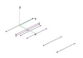
UHF 2-El FD-Yagi - OPTimized (30 Jul 2017)UHF 2-Element Folded Dipole Yagi, OPTIMIZED using nikiml's Python Scripts, analyzed using 4nec2.
UHF Raw Gain = 5.0 to 4.3 dBi, F/B & F/R Ratio = 7.9 to 6.2 dB (POOR) and SWR (300-ohms) Under 2.6 (GOOD). |
| 2045 Visits
21 Items
Shared Album | |
|
 | 3.
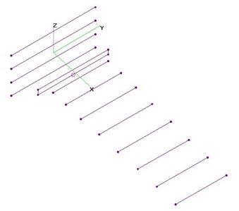
UHF 3-El FD-Yagi - OPTimized (30 Jul 2017)UHF 3-Element Folded Dipole Yagi, OPTIMIZED using nikiml's Python Scripts, analyzed using 4nec2.
UHF Raw Gain = 6.6 to 5.8 to 7.5 dBi, F/B & F/R Ratio Min = 11.3 dB (FAIR) and SWR (300-ohms) Under 2.5 (GOOD). |
| 2896 Visits
15 Items
Shared Album | |
|
 | 4.
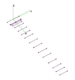
UHF 4-El FD-Yagi - OPTimized (19 Jan 2018)UHF 4-Element Folded Dipole Yagi, OPTIMIZED using nikiml's Python Scripts, analyzed using 4nec2.
UHF Gain = 6.7 to 6.4 to 8.6 dBi, F/B & F/R Minimum = 13.1 dB (FAIR) and SWR Under 1.9 (EXCL). |
| 3312 Visits
15 Items
Shared Album | |
|
 | 5.
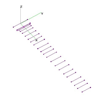
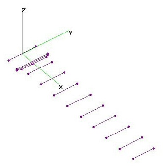
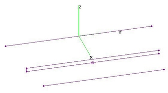
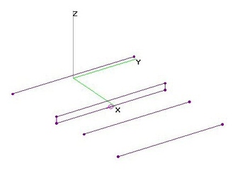
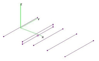
UHF 5-El FD-Yagi - OPTimized (17 Jan 2017)UHF 5-Element Folded Dipole Yagi, OPTIMIZED using nikiml's Python Scripts, analyzed using 4nec2.
Gain, SWR F/B & F/B performance better than CM-4040 5-El FLAT Yagi.
Optimized Boom Length = 22 inches.
UHF Raw Gain = 7.3 to 9.4 to 8.9 dBi, F/B & F/R Ratio Min. = 13.4 dB (FAIR) and SWR under 3.1 (FAIR).
Note well formed Azimuthal Antenna Pattern with 70-50 degree Beamwidth, deceasing with Frequency.
Nearly Bi-Directional Hi-VHF Gain = -0.5 to 0.4 dBi FORWARD and -0.4 to 0.6 dBi to REAR
is slightly HIGHER and nearly OMNI-Directional. But Hi-VHF SWR (300-ohms) is Very EXCESSIVE.
PS: Jointly Optimizing UHF and Hi-VHF should improve Hi-VHF performance, perhaps at expense of UHF. |
| 3199 Visits
28 Items
Shared Album | |
|
 | 6.
UHF 5-El FLAT Yagi - CM-4040 (17 Jan 2017)UHF 5-Element FLAT Yagi, Channel Master CM-4040, analyzed using 4nec2.
I took all measurements directly from Antenna, which includes a built-in 1:1 Balun.
Boom Length = 8.33-in [VERY Compact]
UHF Gain = 7.2 to 5.9 to 7.1 dBi, F/B & F/R Gain = 6.0 to 22.7 dB (POOR-FAIR-EXCL) and SWR (75-ohms) Under 3.1 (FAIR).
Note WIDE BEAMWIDTH Azimuthal Antenna Pattern with 70-60 degree Beamwidth, deceasing with Frequency.
Bi-Directional Hi-VHF Gain = 2.3 to 1.8 dBi FORWARD and 2.5 to 2.2 dBi to REAR is slightly HIGHER.
But Hi-VHF SWR (75-ohms) is Very EXCESSIVE.
=============================================================
Compare to OPTIMIZED UHF 5-El Folded Dipole Yagi, which provides 2-3+ dB higher UHF Gain
and much better F/B & F/R Ratios on lower Channels with OPTIMIZED Boom Length = 22-in:
UHF Raw Gain = 7.3 to 9.4 to 8.9 dBi, F/B & F/R Ratio Min. = 13.4 dB (GOOD) and SWR under 3.1 (GOOD).
Nearly Omni-Directional Hi-VHF Gain = -0.5 to 0.4 dBi FORWARD and -0.4 to 0.6 dBi to REAR
is slightly HIGHER. But Hi-VHF SWR (300-ohms) is Very EXCESSIVE.
PS: Jointly Optimizing UHF and Hi-VHF should improve Hi-VHF performance, perhaps at expense of UHF. |
| 2694 Visits
28 Items
Shared Album | |
|
 | 7.
UHF 6-El FD-Yagi - OPTimized (21 Sep 2017)UHF 6-Element Folded Dipole Yagi, OPTIMIZED using nikiml's Python Scripts, analyzed using 4nec2.
UHF Gain = 7.5 to 10.3 dBi, F/B & F/R Ratio Min. = 13.2 dB (FAIR) and SWR Under 2.0 (EXCL).
Note well formed Azimuthal Antenna Pattern with 70-50 degree Beamwidth, deceasing with Frequency. |
| 2025 Visits
18 Items
Shared Album | |
|
 | 8.
UHF 6-El Asymmetric Dipole Yagi - WA5VJB (20 Feb 2011)UHF 6-Element Asymmetric Dipole analyzed using 4nec2. Dimensions obtained from Kent Britain (WA5VJB)
article at www.popularscience.com, " Cheap and EZ HDTV Antenna Project", Sep 2008.
It provided good Raw Gain across the New UHF Band as well as most of the Old UHF Band above Ch51,
but the Forward Gain fell to about 0 dBi in the vicinity of 542 MHz.
However, the SWR was found to be EXCESSIVE throughout the entire UHF Band and could not be
significantly improved by adjusting the Feedpoint Gap size.
The pictures in the article show the distance between the driver elements INCREASING away from
the boom, which was somewhat different than the dimensional diagram. The 4nec2 model was revised to
also investigate this alternative with different Gap sizes and Element Spacings, but there was very little difference. |
| 8121 Visits
15 Items
Shared Album | |
|
 | 9.
UHF 7-El FD-Yagi - OPTimized (2 Jul 2013)UHF 7-Element Folded Dipole Yagi, Optimized using nikiml's Python Scripts, analyzed using 4nec2.
F/B & F/B performance more consistent than nikiml's 7-El FD-Yagi, but slightly lower Raw Gain.
Boom Length = 21.95 inches.
UHF Raw Gain = 7.8 to 11.2 dBi, F/B & F/R Ratio Minimum = 14.6 dB (FAIR) and SWR under 2.4 (GOOD).
Note well formed Azimuthal Antenna Pattern with 60-50 degree Beamwidth. |
| 6090 Visits
16 Items
Shared Album | |
|
 | 10.
UHF 7-El FD-Yagi - Opt. by Nikiml (6 Jun 2013)UHF 7-Element Folded Dipole (FD) Yagi, 4nec2 from nikiml derived using his Python Optimization Scripts.
Boom Length = 22.55 inches.
UHF Raw Gain = 8.3 to 12.1 dBi, F/B & F/R Ratio Minimum = 10.4 dB (POOR) and SWR under 2.3 (GOOD). |
| 7078 Visits
12 Items
Shared Album | |
|
 | 11.
UHF 8-El FD-Yagi (2ReflRods) - OPTimized (2 Jul 2013)UHF 8-Element Folded Dipole Yagi (with 2 Reflector Rods), Optimized using nikiml's Python Scripts,
analyzed using 4nec2.
Boom Length = 23.21 inches.
UHF Raw Gain = 8.2 to 11.7 dBi, F/B & F/R Ratio Minimum = 20.6 dB (EXCL) and SWR Under 1.6 (EXCL). |
| 6401 Visits
16 Items
Shared Album | |
|
 | 12.
UHF 8-El FLF-Yagi - 300ohm OPTimized (20 Feb 2018)UHF 8-Element Flat-Fed-Loop (FLF) Yagi analyzed using 4nec2 after determining best Dimensions
using nikiml's Python Optimization Scripts.
UHF Gain = 7.9 to 11.7 dBi, F/B & F/R Ratio Min. = 14.2 dB (FAIR) and SWR (300-ohms) under 2.4 (GOOD). |
| 2200 Visits
15 Items
Shared Album | |
|
 | 13.
UHF 12-El FD-Yagi - OPTimized (3 Jul 2013)UHF 12-Element Folded Dipole Yagi, Optimized using nikiml's Python Scripts, analyzed using 4nec2.
Boom Length = 35.28 inches.
UHF Raw Gain = 8.2 to 12.7 dBi, F/B & F/R Ratio Minimum = 15.6 dB (GOOD) and SWR under 3.2 (FAIR). |
| 6248 Visits
17 Items
Shared Album | |
|
 | 14.
UHF 13-El FD-Yagi (2ReflRod) - OPTimized (6 Jul 2013)UHF 13-Element Folded Dipole Yagi (with 2 Reflector Rods), Optimized using nikiml's Python Script
and then analyzed using 4nec2.
Boom Length = 40.2 inches.
UHF Raw Gain = 9.3 to 13.4 dBi, F/B & F/R Ratio Minimum = 22.3 dB (EXCL) and SWR Under 1.7 (GOOD).
Provides a significant improvement in F/B & F/R relative to 12-El FD-Yagi with only one Reflector Rod.
Boom Correction Calculation Examples are given in the below Spread Sheet, based on a variety of sources.
For a 1-in Boom (Circular or Square), the extra Passive Element Half-Length is 0.25-in or LESS,
and for a 1/2-in Boom, the Boom Correction is only 0.1-in or LESS. |
| 7354 Visits
17 Items
Shared Album | |
|
 | 15.
UHF 13-El FD-Yagi (2RR) EqualDirs - OPT (7 Jul 2013)UHF 13-Element Folded Dipole Yagi (2 Reflector Rods), with ALL Directors in Front of the
Second Director having Equal Length, analyzed using 4nec2.
Boom Length = 45.2 inches.
UHF Raw Gain = 8.8 to 14.2 dBi, F/B & F/R Minimum = 21.2 dB (EXCL) and SWR Under 1.6 (EXCL).
Without Equal Director constraint, UHF Raw Gain = 9.3 to 13.4 dBi, hence we picked up 0.8 dB
on higher channels but lost 0.5 dB on lowest and only lost about 1 dB for F/R & F/B Minimum.
The 4.1 dB difference between lowest and higher freqs would disadvantage reception on
lowest Channels, esp. when using a Preamp. |
| 6083 Visits
16 Items
Shared Album | |
|
 | 16.
UHF 13-El FD-Yagi (2ReflRods) - kgb (4 Mar 2010)UHF 13-Element Folded Dipole Yagi (2 Reflector Rods) optimized for Ch14-51+ analyzed using 4nec2.
Dimensions from a post by kgb: http://www.digitalhome.ca/forum/showthread.php?t=119284
Boom Length=37.2-in.
UHF Band Raw Gain = 8.3 to 12.6 dBi, F/B & F/R Ratio Minimum = 14.5 dB (GOOD) and SWR under 2.4.
EDIT (11 Mar 2011): Updated all charts to show extended UHF Band coverage. Added 4nec2 File. |
| 6826 Visits
17 Items
Shared Album | |
|
 | 17.
UHF CM4248 15El FD-Yagi + 14RR Corner (13 Jun 2015)UHF CM4248 15-Element Folded Dipole (FD) Yagi with 14 Reflector Rod (RR) Corner Reflector analyzed
using 4nec2 from a file posted by user <300ohm>, which was based on Measurements by Ken Nist,
posted in an EZNEC file on http://www.hdtvprimer.com/ANTENNAS/comparing.html.
CM3023 is reportedly similar (if not the SAME) as CM4248.
Several Modifications to the Corner Reflector were then analyzed, including adding 12 Reflector Rods
half-way between the existing 14 RRs compared to a pair of Screen Reflectors with the same as well as
larger widths.
Three versions are shown here:
======================================
a) CM4248 15El FD-Yagi (Original) with 14 Reflector Rods in Corner Reflector:
UHF Raw Gain = 12.2 to 14.5 dBi, F/B & F/R Ratio = 18 dB and SWR (300-ohms) Under 2.6.
======================================
b) CM4248 15El FD-Yagi - Plus 12 RR's Half-Way Between 14 RR's in Corner Reflector:
UHF Raw Gain = 12.5 to 15.0 dBi, F/B & F/R Min = 22 dB and SWR (300-ohms) Under 2.9.
=====================================
c) CM4248 15El FD-Yagi - Plus Corner Reflector using a Pair of 23x33-in Screen Reflectors (1x1-in Grid):
UHF Raw Gain = 12.2 to 15.0 dBi, F/B & F/R Ratio Min = 20.0 dB and SWR (300-ohms) Under 2.8.
=====================================
All THREE versions are plotted in the Chart, showing only a MINOR (under 0.5 dB) improvement.
The second and third alternatives are essentially the SAME above 518 MHz, but the Reflector Screen
version has less Gain on lower Frequencies. Wider variations for each version did NOT provide any
improvement. And a variation of the second version with 3 RR's filling in the Apex also did NOT help. |
| 5582 Visits
28 Items
Gallery Album | |
|
 | 18.
UHF 16-El Yagi + 6RR Corner Wade CYD1446 (8 Jan 2017)UHF 16-Element Yagi with 6 Reflector Rod Corner Reflector, approximate 4nec2 Model for Wade CYD-1446,
analyzed using 4nec2 Antenna Modeling Program. Dimensions were provided by Choclab, with some of his photos below.
Two versions are presented below, one without and one WITH the Open Matching Stub Line found directly
behind the Active Dipole Element. There was no significant difference between the two models.
Results are probably "typical" for it's era [esp. given CONSTRAINTS that ALL Director Lengths and Spacings
are the SAME], but are rather underwhelming compared to more modern OPTIMIZED Yagi's, with
Loss of Gain on Upper Channels [which usually need the MOST Gain], poor F/B & F/R Ratios on Upper Channels
and Excessive SWR on both Lower and Upper Channels.
=============================================================
Note that a simplified ALL TUBULAR 4nec2 Model was used for this APPROXIMATE Analysis,
using NEC2 Engine [instead of more accurate NEC4 Engine to Model the Rectangular Directors].
And rather than TRYING to use limited NEC2 Engine to Model all Surfaces in the Open Matching Stub,
an Idealized Open Transmission Line (TL Statement) was used instead to find the OPTIMUM Length and
Characteristic Impedance. |
| 3542 Visits
54 Items
Shared Album | |
|
 | 19.
UHF 17-El Yagi with 6RR's - tfrlic (9 Feb 2019)UHF 17-Element Yagi with 6 Reflector Rod Corner Reflector, per measurements by tfrlic.
Since the Active Dipole Element is very complex [which I suspect will NOT be accurately modeled using
NEC2 engine], for the below 4nec2 Analysis, I replaced it with a much simpler Folded Dipole [adjusting
Length for desired SWR under 2.7], with the same rectangular shape that I've used in nearly all of my
Yagi Optimizations:
https://photobucket.com/gallery/user/tfralic/media/cGF0aDovSU1HXzEyOTQuanBn/?ref=
https://photobucket.com/gallery/user/tfralic/media/cGF0aDovSU1HXzEzMDIuanBn/?ref=
https://photobucket.com/gallery/user/tfralic/media/cGF0aDovYW50LmpwZw==/?ref=
UHF Raw Gain = 10.3 to 14.8 dBi, F/B & F/R Ratio Minimum = 16.4 dB (GOOD) and SWR under 2.6 (EXCL).
=====================================
BOOM CORRECTION CAN BE IGNORED:
Back in 2013, I researched various sources to construct a BOOM CORRECTION Spreadsheet (see below).
Since the 1/2-in Wide FLAT Directors and 3/8-in Diameter Reflector Rods are attached directly to
the 1-in Square Boom, the Measured Dimensions "should" be REDUCED by about 0.25-in when modeled
in 4nec2 to account for the absence of the Boom proximity, which is NOT modeled in 4nec2.
Since Boom Correction is so small, I have ignored it...which would have moved the Frequency Response
Curve higher ever so slightly. |
| 2105 Visits
16 Items
Shared Album | |
|
 | 20.
UHF 18-El FD-Yagi (2ReflRods) - OPT (21 Jul 2013)UHF 18-Element Folded Dipole Yagi with 2 Reflector Rods, Optimized using nikiml' Python Scripts
and analyzed using 4nec2.
Boom Length = 68.3 inches.
UHF Raw Gain = 10.0 to 14.9 dBi, UHF F/B & F/R Minimum = 24.3 dB and SWR (300-ohms) Under 1.8. |
| 5832 Visits
17 Items
Shared Album | |
|
 | 21.
UHF 18-El Yagi from snowman53 (26Aug2009)UHF 18-Element Yagi (663 MHz Design Freq) analyzed using 4nec2.
Yagi design is from postings by snowman53.
Boom Length = 85.75 inches. |
| 8737 Visits
19 Items
Shared Album | |
|
 | 22.
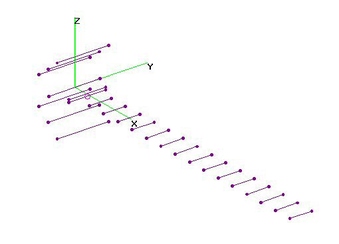
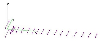
UHF 25-El FD-Yagi (2ReflRods) - OPT (21 Jul 2013)UHF 25-Element Folded Dipole Yagi (2 Reflector Rods), Optimized with nikiml's Python Scripts, analyzed using 4nec2.
Boom Length = 95.7 inches.
UHF Raw Gain = 10.8 to 16.2 dBi, UHF F/B & F/R Minimum = 24.4 dB and SWR (300-ohns) Under 1.9. |
| 6457 Visits
17 Items
Shared Album | |
|
 | 23.
UHF 91XG Corner-FD-Yagi (24Aug2009)UHF Antennas Direct 91XG (aka XG91) 23-Director Corner-FD-Yagi analyzed using 4nec2.
[Folded Dipole, 1-ea Director-Rod, 22-ea Bowtie Directors (ALL SAME SIZE) & a Corner Reflector.]
Boom Length=90.2-in.
RevA: UHF Raw Gain = 11.5 dbi (470 MHz) to 16.9 dBi (698 MHz) to 17.8 dbi (758 MHz),
F/R & F/B Ratio Min = 19.9 dB (Excellent) and SWR (300-ohms) Under 3.0 (Fair).
RevF: UHF Raw Gain = 11.3 dbi (470 MHz) to 16.6 dBi (698 MHz) to 17.5 dbi (758 MHz),
F/R & F/B Ratio Min = 19.8 dB (Excellent) and SWR (300-ohms) Under 2.3 (Excellent).
Hi-VHF Raw Gain plots show a reasonable amount of Gain, with more toward the REAR.
SWR is very excessive, which may or may not cause problems, esp. on weak channels.
However, a couple years ago A-D changed to a PCB Balun (vice usual Hybrid Transformer)
which has very high loss on VHF frequencies....so Hi-VHF charts only apply to old versions.
XG91a.nec file was converted (by 300ohm) from Ken Nist's EZNEC file:
http://www.wuala.com/300ohm/Documents
300ohm also posted a 4nec2 file for a 91XG with SIX additional Directors.
Boom Length=122.1-in.
I added some FR and RP statements and a variable SOURCE wire radius to adjust AGT=1.0
for both UHF and Hi-VHF (XG91a_RevA.nec). The latest, XG91a_RevF.nec, removed some
extraneous wires from the Directors, eliminating "Sharp Angle" Warnings and changed
SOURCE Wire so AGT=1.0 and NO Errors or Warnings.
NOTE: There are several variations of the XG91/91XG from different manufacturers.
Carefully check your dimensions against Ken Nist's model...esp. if you think you have a 75-ohm balun.
EDIT (14Nov2012): All Elevation (Vertical Plane) Charts were mislabeled as "Azimuthal".
Chart labels corrected and added Azimuthal Chart set.
Added Rev E 4nec2 version with AGT=1.0 and NO Errors and Only Warnings
when Run AGT and NONE when Run 4nec2 file or Segment Test (weird).
EDIT (8Jan2012): Incorrect RevC 4nec2 file had erroneously been uploaded (was RevD).
Uploaded correct RevC 4nec2 file.
EDIT (22Aug2013): Uploaded RevF 4nec2 file which eliminated ALL Warnings. Note minor
Raw Gain differences (lower than A-D's published modeling results) and SWR Max = 2.3
(better agreement with A-D's modeling results):
http://www.antennasdirect.com/cmss_files/attachmentlibrary/Technical%20Data%20PDF%27s/91XG-TDS.pdf
EDIT (24Nov2014): Added Ch2-13 Performance Charts (Items 46-48). |
| 11190 Visits
55 Items
Shared Album | |
|
 | 24.
UHF 91XG - Wider Corner Reflector (21 Aug 2013)UHF Antennas Direct 91XG with WIDER Corner Reflector, but SAME Height analyzed using 4nec2.
Minimal improvement in Raw Gain.
F/B & F/R Ratios somewhat higher, but ONLY on lower channels.
Due to poor performance, I didn't waste time adjusting First Director-Rod to improve SWR. |
| 5384 Visits
9 Items
Shared Album | |
|
 | 25.
UHF 91XG - Wider Bowties, Better Ch14-51 (18 Aug 2013)UHF Antennas Direct 91XG Mod: Wider Bowties for Better Performance on NEW Ch14-51 UHF Band.
Results for THREE versions found below:
a) Final Design with Design Parameters adjusted for Max Gain on 698 MHz with low SWR provides
about 1 dB improvement across entire UHF Band compared to Ken Nist's Original 91XG EZNEC Model.
UHF Raw Gain = 12.5 dBi (470 MHz) to 17.8 dBi (698 MHz) (after -0.1 dB AGT Correction),
F/R & F/B Ratio Min = 20.9 dB (Excellent) and SWR (300-ohms) Under 2.4 (Excellent).
Compare to Unmodified 91XG:
UHF Raw Gain = 11.5 dbi (470 MHz) to 16.9 dBi (698 MHz) to 17.8 dbi (758 MHz), F/R & F/B Ratio
Min = 19.9 dB (Excellent) and SWR (300-ohms) Under 3.0.
[A bit high on higher channels...but A-D's presumably higher accuracy model finds SWR Max=2.5.]
To Widen the Bowties in the 4nec2 Model, THREE new Wires were added to each of the four tips on
ALL 22 Bowties. Outer Width-to-Centerline parameter "Ymax = 3*Zmax = 3*2.275 = 6.825" (+/- 0.1-in)
was adjusted to find the "best" combination of Raw Gain, F/B & F/R Ratios and SWR, trying to have
Max Gain fall on 698 MHz. Final iteration of 4nec2 "Parameter Sweep" Charts are included below.
To adjust SWR to acceptable levels, it ALSO was necessary to SHORTEN the FIRST Director-Rod
[which primarily controls SWR] from an Overall Width of 6.28-inches down to just 6.0-inches (+/- 0.1-in).
Three actual implementations come to mind:
1) Cut out a piece of sheet metal in the shape of each outer "Tip" and butt-weld it to the existing Bowtie.
[Rigidity & Reliability could be improved by tack welding a metal rod(s) across the joint.]
2) Cut out a larger new "Tip", including a long overlap so that they could be drilled for two rivets.
3) Since it is not NECESSARY to fill in the area, form a simple Outline Wire and tack weld to existing Bowtie.
======================================
b) Alternative Design with more Gain on lower channels at expense of Gain on highest channels
improves Gain on lower channels by about 2 dB compared to unmodified 91XG.
UHF Raw Gain = 13.7 dBi (470 MHz) to 17.3 dBi (626 MHz) to 15.0 dBi (698 MHz) (after -0.1 dB
AGT Correction), F/R & F/B Ratio Min = 17.9 dB (Excellent) and SWR (300-ohms) Under 2.7 (Excellent).
To Widen the Bowties in the 4nec2 Model, THREE new Wires were added to each of the four tips on
ALL 22 Bowties. Outer Width-to-Centerline parameter "Ymax = 3*Zmax = 3*2.55 = 7.65" (+/- 0.05-in)
was adjusted to find the "best" combination of Raw Gain, F/B & F/R Ratios and SWR, which resulted in
Max Gain falling on 626 MHz.
To adjust SWR to acceptable levels, it ALSO was necessary to SHORTEN the FIRST Director-Rod
[which primarily controls SWR] from an Overall Width of 6.28-inches down to just 5.04-inches (+/- 0.1-in).
======================================
c) Preliminary Proof of Concept, adding a SINGLE Wire "Spike" to the 4 ends on each Bowtie Director:
UHF Raw Gain = 12.7 dBi (470 MHz) to 17.7 dBi (698 MHz), F/R & F/B Ratio Minimum = 20.2 dB
(Excellent) and SWR (300-ohms) Under 4.0 (a bit high on higher channels).
Background:
As a preliminary, proof of concept, additional wires were initially added to extend the Width
of the Active Folded Dipole...but this did not improve performance (but might in combination).
Instead, a single wire, variable Length "Spike" was added to the four ends on each
of the 22 Bowtie Directors to extend their Width, thereby lowering their operating frequency.
Since I couldn't get nikiml's Python Optimization Scripts to run correctly, I tried different
values for the "Spike" Length to find the "best" value (L = 1.167 inches).
Initially I tried 1/4-in wire diameter, presuming it would be simply tack welded in place. But
4nec2 declared a bunch of "Fat Wire" intersecting wire Warnings, so I changed to AWG10.
I also tried both my RevA and RevE versions of Ken Nist's original EZNEC, where RevE eliminated
the many "Sharp Angle" Warnings in RevA....but still wouldn't run Python Scripts correctly.
EDIT (27Aug2013): Fixed 6th Bowtie Director from the front, in all three versions the four
Tip Extensions were erroneously located at X=62.42 vice 62.62, leaving them unconnected.
Impact on results was negligible (about 0.1 dB), except in version b) the higher frequency
F/R Ratio improved several dB and in c) SWR improved from Max=4.0 to Max=3.0.
EDIT (28Aug2013): Corrected above summary, Original Width of First Director-Rod
was 2*Yd=2*3.12=6.28-in (not 8.12-in). |
| 153608 Visits
50 Items
Shared Album | |
|
 | 26.
UHF 91XG - Taller Corner Reflector (23 Aug 2013)UHF Antennas Direct 91XG modified for TALLER Corner Reflectors analyzed using 4nec2.
Investigations revealed that Ken Nist's model for the Corner Reflector was preventing
Python Optimization Scripts from running correctly. To greatly reduce the number of
Wires added to the RevF model, I decided to replace the Corner Reflector with a
20 Reflector Rods "equivalent". An all Reflector Rod replacement would also keep
wind resistance to a minimum, an important consideration with a much larger "Wind Vane".
THREE versions were analyzed, with only MINOR (0.4 & 0.7 dB) Raw Gain improvements:
a) 91XG RevF version with Ken Nist's Corner Reflector replaced by 20 Reflector Rods
to verify that results are in general agreement.
UHF Raw Gain = 11.2 dBi (470 MHz) to 16.6 dBi (698 MHz),
F/R Ratio Minimum = 24.2 dB and SWR under 2.3.
b) 91XG RevF version with 6 Reflector Rods added with roughly same separation
as originals along a +/- 48-degree line.
UHF Raw Gain = 11.6 dBi (470 MHz) to 16.7 dBi (698 MHz),
F/R Ratio Minimum = 24.5 dB and SWR under 2.3.
c) 91XG RevF version with 12 Reflector Rods added.
UHF Raw Gain = 11.9 dBi (470 MHz) to 16.8 dBi (698 MHz),
F/R Ratio Minimum = 25.8 dB and SWR under 2.3. |
| 5433 Visits
30 Items
Shared Album | |
|
 | 27.
Ch14-17 15El FD-Yagi + 14RR Corner - OPT (29 Sep 2013)Ch14-17 15-Element Folded Dipole Yagi with (14 Reflector Rods) Corner Reflector analyzed
using 4nec2. Dimensions determined using nikiml's Python Optimization Scripts, incl.
Corner Angle and location of Yagi's Reflector relative to the Corner (+/- 10 inches),
resulting in Yagi Reflector (and hence entire Yagi) being offset 7.1-in Forward of the
Corner Reflector's (imaginary) Apex.
Boom Length = 105-inches, , Reflector Rod Width=35.9-in, Corner Angle=40.4-deg
and Xsep=8.6-in, Rod-Rod Separation (Projection onto the X-Axis).
Ch14-17 Raw Gain = 18.0 dBi, F/B & F/R Ratio Min = 23.3 dB and SWR under 1.2.
NOTE: BETTER than same/longer Boom Length versions with MORE Directors and Corner Rods. |
| 5890 Visits
13 Items
Shared Album | |
|
 | 28.
Ch14-17 18El FD-Yagi + 10RR Corner - OPT (7 Oct 2013)Ch14-17 18-Element Folded Dipole Yagi with (10 Reflector Rod) Corner Reflector analyzed
using 4nec2. Dimensions (see 4nec2 File) determined using nikiml's Python Optimization Scripts.
Boom Length = 112in was intentionally constrained by an non-linear exponential term
in the Python Optimization Script's Target Function. Without this constraint an
excessively long 140-in Boom Length provided only another 0.5 dB of Gain (not shown).
On Ch14 Raw Gain = 17.4 dBi, F/R & F/B Ratio under 33.0 dB and SWR (300-ohms) under 1.1.
Note that additional Directors DEGRADED Gain vs Ch14-17 15El FD Yagi + 14RR Corner. |
| 4296 Visits
15 Items
Shared Album | |
|
 | 29.
Ch14-17 18El FD-Yagi + 14RR Corner - OPT (7 Oct 2013)Ch14-17 18-Element Folded Dipole Yagi with Corner Reflector (14 Reflector Rods) analyzed using 4nec2.
Dimensions (see 4nec2 File) determined using nikiml's Python Optimization Scripts.
Boom Length = 111in was intentionally constrained by an non-linear exponential term
in the Python Optimization Script's Target Function. Without this constraint an
excessively long 146-in Boom Length provided only another 0.3 dB of Gain (not shown).
On Ch14 Raw Gain = 17.2 dBi, F/B & F/R Ratio = 25.0 dB and SWR (300-ohms) under 1.1.
Note the small DEGRADATION compared to using only 10 RR for SAME Boom Length & 18-Elements.
Note that additional Directors DEGRADED Gain vs Ch14-17 15El FD Yagi + 14RR Corner. |
| 4406 Visits
15 Items
Shared Album | |
|
 | 30.
Ch14-17 18El FD-Yagi + 20RR Corner - OPT (7 Oct 2013)Ch14-17 18-Element Folded Dipole Yagi with Corner Reflector (20 Reflector Rods) analyzed using 4nec2.
Dimensions (see 4nec2 File) determined using nikiml's Python Optimization Scripts.
Two alternaive Geometries were investigated: the Conventional Corner Angle
Reflector and a Free Form Search for the "Best" arrangement of RANDOMLY placed Reflector
Rods, subject to just a few placement Constraints.
Boom Length = 112-in was intentionally constrained by an non-linear exponential term
in the Python Optimization Script's Target Function.
On Ch14 Raw Gain = 18.6 dBi, F/B & F/R Ratio = 29.9 dB and SWR (300-ohms) under 1.1.
######################################
a) FREE FORM PLACEMENT OF REFLECTOR ROD PAIRS:
Dimensions determined using nikiml's Python Optimization Scripts, using RANDOM placements
of Reflector Rod (RR) PAIRS (symmetric about the Boom) where Optimizer randomly selects
Y-Coordinate Length (12 to 50-in) and X-Z Coordinates within fol. CONSTRAINTS:
i) 18-El Yagi no Longer than about 110-in,
ii) 4 RR Pair between X = -10 and 20-in and Z = +/- 36-in,
iii) 3 RR Pair between X = -10 and 40-in and Z = +/- 40-in,
iv) 3 RR Pair between X = -10 and 150-in and Z = +/- 40-in.
Final DOUBLE-ANGLE configuration is shown below, with five RR pairs in nearly Vertical Row
behind the Yagi's Reflector, one RR Pair in close proximity above/below the Active Folded Dipole,
with the remaining one SHORT RR pair and 3 LONG RR pairs further forward, on a rough approximation
to a Double-Angle Reflector, although proximity to Max-Z may be limiting their ultimate configuration.
UHF Raw Gain = 18.0 dBi on Ch14-17 is LESS than Corner Reflector above.
[Adjusting Optimization Parameters can probably improve on this Preliminary FIRST RUN.]
######################################
b) PARABOLA PLUS ADDITIONAL RR REFLECTOR:
Prior to forming final configuration above, there was a preliminary configuration
with five RR pairs forming a Parabolic shape in close vicinity of Yagi's Rear Reflector,
which is also shown below. UHF Raw Gain was only somewhat lower: 17.9 dBi.
CORRECTION (22 Nov 2013): Images were ALL replaced by 20 RR (vice incorrect 14 RR) version.
ADDENDUM (22 Nov 2013): First, preliminary run for RANDOM placement of Reflector Rods
was uploaded. Additional runs need to be conducted to see if Gain can come closer to Corner version. |
| 5161 Visits
30 Items
Gallery Album | |
|
 | 31.
Ch14-19 18El FD-Yagi + 20RR Corner - OPT (23 Sep 2013)Ch14-19 21-Element Folded Dipole Yagi with (20 Reflector Rod) Corner Reflector analyzed
using 4nec2. Dimensions were determined using nikiml's Python Optimization Scripts,
incl. Corner Angle and location of the Yagi's Reflector relative to Corner (+/- 6 inches),
resulting in Yagi Reflector (and hence entire Yagi) being offset 2.75-in Forward of the
Corner Reflector's (imaginary) Apex.
Boom Length = 121-in, Reflector Rod Width=35.8-in, Corner Angle=41.8-deg
and Xsep=5.6-in, Rod-Rod Separation (Projection onto the X-Axis).
Ch14-19 Raw Gain = 17.8 to 18.0 dBi, F/B & F/R Ratio Min=23.7 dB & SWR (300-ohms) under 1.7. |
| 4464 Visits
13 Items
Shared Album | |
|
 | 32.
Ch14-19 21El FD-Yagi + 20RR Corner - OPT (20 Sep 2013)Ch14-19 21-Element Folded Dipole Yagi with 20 Reflector Rod Corner Reflector analyzed using 4nec2.
Dimensions were determined (incl. Corner Angle and Length of Yagi Reflector in the Apex)
using nikiml's Python Optimization Scripts.
Dimensions are found in the 4nec2 File: Boom Length = 97-inches.
Corner Reflector Width=37.06-in, Corner Angle (to X-Axis)=49.54-deg and Xsep=2.83-in
(projection onto X-Axis of Reflector Rod-Rod Separation).
Ch14-19 Raw Gain = 16.1 to 16.2 dBi,
F/B & F/R Ratio Min = 30.5 dB and SWR (300-ohms) Under 1.7.
A Parameter Sweep was conducted to determine Optimum value for S0, the location of the
Yagi Reflector (and hence the entire Yagi) relative to the Corner's Apex, finding little
difference for S0 = 0.0 to 1.0, so position of Yagi relative to Corner is indeed Optimum. |
| 4867 Visits
12 Items
Shared Album | |
|
 | 33.
Ch22 9-El FD-Yagi - 300ohm OPTimized (12 Jun 2016)Ch22 9-Element Folded-Dipole (FD) Yagi (518-524 MHz) analyzed using 4nec2 [see *.nec.doc file below].
Dimensions, incl. Loop Width and Height, were determined using nikiml's Python Optimization Scripts.
It is Optimized for 8 MHz Bandwidth (to ensure no problems on the band edges...and if ReScaled
Upwards) centered on Ch22 [518-524 MHz].
Note that nikiml's EVAL function [for Horizontally Polarized signals, listed in summary below] calculates
somewhat higher F/B & F/R Ratios than 4nec2 Chart [for TOTAL Gain = Horizontal + Vertical Gains].
Ch22 9-El FD-Yagi - 300ohm OPTimized:
Ch22 Raw Gain = 12.9 to 13.1 dBi, F/B & F/R Ratio Min. = 34.3 dB and SWR (300-ohms) Under 1.5.
BTW: Gain for Optimized 75-ohm FD-Yagi was not quite as Good.
Also note the F/B Ratio NULL directly to the Rear (which you might have to STEER toward severe Interference).
Forward Sidelobes are quite good, being suppressed about 21 dB on 521 MHz.
Note that there is a Deep NULL in the Elevation Pattern, which could be used to advantage to suppress
Ground Bounce using an Antenna Tilter to aim the Antenna somewhat UPWARDS.
BOOM LENGTH = 1042-mm, and is UNCONSTRAINED.
BTW: Gain for 9-El FD-Yagi Optimized for 75-ohm was not quite as Good.
Dimensions incl. Min-Max Search Range (all in cm) from below 4nec2 Text File [Variable SYmbol Statements]:
' Cumulative Element Spacings (cm): [May round all Dimensions to nearest 0.1-cm]
SY S1=0
SY D2=10.90266' 3, 20
SY S2=S1+D2
SY D3=3.002401' 3, 20
SY S3=S2+D3
SY D4=8.143348' 3, 20
SY S4=S3+D4
SY D5=14.07628' 3, 20
SY S5=S4+D5
SY D6=12.63379' 3, 20
SY S6=S5+D6
SY D7=19.3514' 3, 20
SY S7=S6+D7
SY D8=19.94919' 3, 20
SY S8=S7+D8
SY D9=16.46316' 3, 20
SY S9=S8+D9
'
' Element Lengths (cm):
SY L1=29.79505' 15, 40
SY L2=30.69886' 15, 40
SY L3=25.98962' 15, 40
SY L4=24.79525' 15, 40
SY L5=23.60214' 15, 40
SY L6=22.73211' 15, 40
SY L7=22.03925' 15, 40
SY L8=23.61077' 15, 40
SY L9=21.62618' 15, 40
'
' Distance of Yagi above & below Center line (NOT USED IN THIS MODEL):
SY Zyag=0
SY Relem=0.3175
SY RACT=Relem' Yagi Active Element Radius (in cm for 1/4-in O.D.)
' Half Width between Long Elements in Folded Dipole:
SY FW=1.25
SY FD=FW/2' Distance between Center of Boom and Folded Dipole Element
SY Gap=2.5 |
| 3174 Visits
18 Items
Shared Album | |
|
 | 34.
Ch22 9-El FLF-Yagi - 300ohm OPTimized (12 Jun 2016)Ch22 9-Element Flat-Loop-Fed (FLF) Yagi (518-524 MHz) analyzed using 4nec2 [see *.nec.doc file below].
See Dr. Hidetsugu Yagi holding an example: https://www.jpo.go.jp/seido_e/rekishi_e/hidetsugu_yagi.htm
It is Optimized for 8 MHz Bandwidth (to ensure no problems on the band edges...and if ReScaled Upwards)
centered on Ch22 [518-524 MHz].
Dimensions were determined using nikiml's Python Optimization Scripts. Similar to Folded Dipole, except
rotated (with SOURCE towards REAR) so Co-Planar with rest of Yagi. ALL X,Y,Z Dimensions Optimized.
Note that nikiml's EVAL function [for Horizontally Polarized signals, listed in summary below] calculates
somewhat higher F/B & F/R Ratios than 4nec2 Chart [for TOTAL Gain = Horizontal + Vertical Gains].
Ch22 9-El FLF-Yagi - 300ohm OPT
Ch22 Raw Gain = 13.2 to 13.4 dBi, F/B & F/R Ratio Min. = 40.2 dB and SWR (300-ohms) Under 1.7.
Forward Sidelobes are quite good, being suppressed about 22 dB on 521 MHz.
Note that there is a Deep NULL in the Elevation Pattern, which could be used to advantage to suppress
Ground Bounce using an Antenna Tilter to aim the Antenna somewhat UPWARDS.
BOOM LENGTH = 1019-mm, and is UNCONSTRAINED.
Compare to Alternative Designs for similar 9-El Yagis: use pull-down Navigation Menu above:
Ch22 9-El FD-Yagi - 300ohm OPTimized:
Ch22 Raw Gain = 12.7 to 12.9 dBi, F/B & F/R Ratio Min. = 26.4 dB and SWR (300-ohms) Under 2.2.
Ch22 9-El FD-Yagi - 300-ohm K7MEM:
Ch22 Raw Gain = 13.3 to 13.4 dBi, F/B & F/R Ratio Min. = 14.3 dB and SWR (300-ohms) = Under 1.4.
BOOM LENGTH = 1045-mm (41-1/8 inches).
Ch22 9-El FD-Yagi - 75-ohm MTM Scientific:
Ch22 Raw Gain = 11.5 to 11.4 dBi, F/B & F/R Ratio Min. = 17.0 dB and SWR (75-ohms) = 3.3 to 5.0 is EXCESSIVE.
BOOM LENGTH = 760-mm.
A Yagi has about the SAME Gain whether driven by a Stick Dipole or a conventional Folded Dipole:
http://photos.imageevent.com/holl_ands/yagis/k6sti//Hi-VHF%205-El%20K6STI%20SweptDE%20Yagi%20%20-%20Compare%20OrigandRevAandFD%20Gain.jpg
Or use Pull-Down Menu above to Navigate to Analysis of my Optimized Hi-VHF 5-El FD-Yagi vs Stick Dipole
Yagi Optimized by K6STI.
HOWEVER, when the additional Element in the Flat-Loop-Fed Yagi is rotated to be Co-Planar, it becomes
ONE MORE ELEMENT that can add Gain to the Traveling Wave Signal....it ALSO makes the Yagi LONGER,
which we've learned also indicates MORE GAIN....so perhaps we should call this a 10-El Yagi, where
the second and third Elements happen to be interconnected at their extremities, forming a Loop.
Note that Flat-Loop-Fed (FLF) Yagi's date back as "PRIOR ART" at least as early as 1940's.
Justin Johnson (G0KSC) has (FWIW) Copyrighted some "similar" Loop Fed Array (LFA) Yagis, designed
to have a VERY LOW IMPEDANCE [under 50-ohms], but until he has an approved PATENT, it's up
in the air as to WHAT UNIQUE FEATURE(S) make it an LFA.
More info on this subject: http://www.hamradio.me/antennas/loop-fed-array-lfa-planar-yagi-uda.html
BTW: This Random Optimization Search found Circumference = 51.1-cm [wavelength = 586 MHz] which
is NOT one-wavelength at 512 MHz CM [57.58-cm] or anywhere else in the desired 518-524 MHz Band.
Dimensions incl. Min-Max Search Range (all in cm) from below 4nec2 Text File [Variable SYmbol Statements]:
' Cumulative Element Spacings (cm): [May round all Dimensions to nearest 0.1-cm]
SY S1=0
SY D2=3.482158' 1, 20
SY S2=S1+D2
SY D2F=1.001045' 1, 20
SY S2F=S2+D2F' LFA LOOP FORWARD ELEMENT [LOOP Spacing in Preceeding]
SY D3=2.981495' 1, 20
SY S3=S2F+D3
SY D4=13.40711' 2, 20
SY S4=S3+D4
SY D5=16.09583' 2, 20
SY S5=S4+D5
SY D6=7.782681' 2, 20
SY S6=S5+D6
SY D7=19.70989' 2, 20
SY S7=S6+D7
SY D8=18.18249' 2, 20
SY S8=S7+D8
SY D9=19.24685' 2, 20
SY S9=S8+D9
'
' Element Lengths (cm):
SY L1=28.79224' 15, 40
SY L2=24.55138' 15, 40
SY L3=26.15635' 15, 40
SY L4=24.56356' 15, 40
SY L5=21.93556' 15, 40
SY L6=22.78706' 15, 40
SY L7=23.34455' 15, 40
SY L8=23.2712' 15, 40
SY L9=19.78836' 15, 40
'
' Z-Coord Distance of Yagi above & below Center line:
SY Zyag=0.0
' Z-Coord Distance of FLF Loop ELement above or below Center line:
SY Zloop=0.0
SY Relem=0.3175 ' Yagi Passive Element Radius (in cm for 1/4-in O.D.)
SY RACT=Relem ' Yagi Active Element Radius (in cm for 1/4-in O.D.)
' Width between Long Elements in Folded Dipole: [ALSO ALLOWS FOR SQUARE/RECTANGULAR LOOP DRIVERS]
SY FW=6.35546' 1, 16
SY FD=FW/2 ' Distance between Center of Boom and Folded Dipole Element
SY Gap=2.5 ' Feedpoint Gap (in cm for 1-in Gap) |
| 4093 Visits
18 Items
Shared Album | |
|
 | 35.
Ch22 9-El FD-Yagi - 75ohm MTM Scientific (12 Jun 2016)Ch22 9-Element Folded Dipole Yagi (518-524 MHz) analyzed using 4nec2 [see *.nec.doc file below]. Design Dimensions
for 75-ohm Yagis from fol. MTM Scientific UHF TV Antenna Kit Article: http://www.mtmscientific.com/yagi.pdf
It is Optimized for 8 MHz Bandwidth (to ensure no problems on the band edges...and if ReScaled Upwards)
centered on Ch22 [518-524 MHz].
Ch22 9-El FD-Yagi - 75-ohm MTM Scientific:
Ch22 Raw Gain = 11.5 to 11.4 dBi, F/B & F/R Ratio Min. = 17.0 dB and SWR (75-ohms) = 3.3 to 5.0 is EXCESSIVE.
BOOM LENGTH = 760-mm.
Unfortunately the MTM Scientific Designs (like similar "Formula Driven" Yagi Designs such as K7MEM), are NOT OPTIMIZED.
Although Gain Curve was VERY FLAT, F/B & F/R Ratios were Best on 502-508 MHz [vice desired 518-524 MHz]
and SWR Minimum is ACTUALLY near 498 MHz rather than desired 521 MHz.
[BTW: Since MTM article assumed NON-METALLIC Boom, no Boom Corrections are involved.]
Compare to OPTIMIZED Designs for similar 9-El Yagis: use pull-down Navigation Menu above:
Ch22 9-El FD-Yagi - 300ohm OPTimized:
Ch22 Raw Gain = 12.7 to 12.9 dBi, F/B & F/R Ratio Min. = 26.4 dB and SWR (300-ohms) Under 2.2.
BTW: Gain for Optimized 75-ohm FD-Yagi was not quite as Good. And note that F/B & F/R Ratios could be
improved at the expense of a small amount of Forward Gain and/or slightly higher SWR.
Ch22 9-El FLF-Yagi [Flat-Loop-Fed] - 300ohm OPTimized:
Ch22 Raw Gain = 13.2 to 13.4 dBi, F/B & F/R Ratio Min. = 40.2 dB and SWR (300-ohms) Under 1.7.
Dimensions (all in cm) from below 4nec2 Text File:
' Cumulative Element Spacings (cm):
SY S1=0
SY D2=7.2
SY S2=S1+D2
SY D3=5.7
SY S3=S2+D3
SY D4=6.8
SY S4=S3+D4
SY D5=7.9
SY S5=S4+D5
SY D6=9.4
SY S6=S5+D6
SY D7=11.0
SY S7=S6+D7
SY D8=12.8
SY S8=S7+D8
SY D9=15.2
SY S9=S8+D9
'
' Element Lengths (cm):
SY L1=28.8
SY L2=27.3
SY L3=26.3
SY L4=24.7
SY L5=23.8
SY L6=23.6
SY L7=21.6
SY L8=21.5
SY L9=19.7
'
' Distance of Yagi above & below Center line (NOT USED IN THIS MODEL):
SY Zyag=0
'
SY Relem=0.3175 ' Yagi Passive Element Radius (in cm for 1/4-in O.D.)
SY RACT=Relem ' Yagi Active Element Radius (in cm for 1/4-in O.D.)
SY FW=1.25 ' Width between Long Elements in Folded Dipole (in cm for 1/2-in)
SY FD=FW/2 ' Distance between Center of Boom and Folded Dipole Element
SY Gap=2.5 ' Feedpoint Gap (in cm for 1-in Gap) |
| 2476 Visits
19 Items
Shared Album | |
|
 | 36.
Ch22 9-El FD-Yagi - 300ohm K7MEM (3 Jul 2016)Ch22 9-Element Folded Dipole Yagi (518-524 MHz) analyzed using 4nec2 [see *.nec.doc file below].
Design Dimensions from rabbit73 post for 11-El Yagi (see last Image), and K7MEM Design for 9-El
simply drops two front Directors. Calculated using fol. K7MEM Website:
http://www.k7mem.com/Electronic_Notebook/antennas/yagi_vhf.html
Note that K7MEM Dimensions [for Cutting Elements] must be SHORTENED by the "Boom Correction"
= BC * Element Diameter, when 4nec2 Model is constructed WITHOUT the METAL Boom, where BC=0.666.
Boom Correction for ACTIVE Element is derated by 50% due to being mounted ABOVE the Boom.
Ch22 9-El FD-Yagi - 300-ohm K7MEM:
Ch22 Raw Gain = 13.3 to 13.4 dBi, F/B & F/R Ratio Min. = 14.3 dB and SWR (300-ohms) = Under 1.4.
BOOM LENGTH = 1045-mm (41-1/8 inches).
Unfortunately, K7MEM (like other "Formula Driven" Designs), are NOT OPTIMIZED [poor F/B & F/R Ratios].
Although Gain Curve was VERY FLAT, F/B & F/R Ratios were Best well away from desired 518-524 MHz
and SWR Curve for 200-ohms is better than 300-ohms, although Both are "Acceptable" [not always true].
Compare to OPTIMIZED Designs for similar 9-El Yagis: use pull-down Navigation Menu above:
Ch22 9-El FD-Yagi - 300ohm OPTimized:
Ch22 Raw Gain = 12.7 to 12.9 dBi, F/B & F/R Ratio Min. = 26.4 dB and SWR (300-ohms) Under 2.2.
BTW: Gain for Optimized 75-ohm FD-Yagi was not quite as Good. And note that F/B & F/R Ratios could be
improved at the expense of a small amount of Forward Gain and/or slightly higher SWR.
Ch22 9-El FLF-Yagi [Flat-Loop-Fed] - 300ohm OPTimized:
Ch22 Raw Gain = 13.2 to 13.4 dBi, F/B & F/R Ratio Min. = 40.2 dB and SWR (300-ohms) Under 1.7. |
| 2630 Visits
15 Items
Shared Album | |
|
 | 37.
Ch22 11-El FD-Yagi - 300ohm K7MEM (4 Jul 2016)Ch22 11-Element Folded Dipole Yagi (518-524 MHz) analyzed using 4nec2 [see *.nec.doc file below].
Design Dimensions for 11-El Yagi from rabbit73 post, calculated using fol. K7MEM Website:
http://www.k7mem.com/Electronic_Notebook/antennas/yagi_vhf.html
Note that K7MEM Dimensions [for Cutting Elements] must be SHORTENED by the "Boom Correction"
= BC * Element Diameter, when 4nec2 Model is constructed WITHOUT the METAL Boom, where BC=0.666.
Boom Correction for ACTIVE Element is derated by 50% due to being mounted ABOVE the Boom.
Ch22 11-El FD-Yagi - 300-ohm K7MEM:
Ch22 Raw Gain = 14.3 to 14.5 dBi, F/B & F/R Ratio Min. = 16.7 dB and SWR (300-ohms) = Under 1.8.
BOOM LENGTH = 1433-mm (56-13/32 inches).
Unfortunately, K7MEM (like other "Formula Driven" Designs), are NOT OPTIMIZED [poor F/B & F/R Ratios].
Gain, F/B & F/R Ratios were Best on 529 MHz, vice desired 518-524 MHz and SWR Curve for 200-ohms
is better than 300-ohms, although Both are "Acceptable" [not always true]. |
| 2596 Visits
18 Items
Shared Album | |
|
 | 38.
Ch30 18El FD-Yagi + 14RR Corner (9 Aug 2014)Ch30 18-Element Folded-Dipole Yagi with 14-Reflector Rod Corner Reflector analyzed using 4nec2.
Dimensions per nikiml's Python Optimization Scripts. Boom Length = 111.4-in, Height = 85.75-in.
Ch30 Raw Gain = 18.5 dBi, F/B & F/R Ratio Minimum = 32 dB and SWR (300-ohms) Under 1.2. |
| 3917 Visits
13 Items
Gallery Album | |
|
 | 39.
Ch45-51 12-El FD-Yagi - OPTimized (11 May 2015)Ch45-51 12-Element Folded Dipole Yagi with Optimized Dimensions using nikiml's Python Scripts.
BoomLength = 48.3-in.
Ch45-51 Raw Gain = 13.7 to 14.3 to 13.9 dBi, F/B & F/R Min = 27.0 dB and SWR (300-ohms) Under 1.4. |
| 35040 Visits
15 Items
Gallery Album | |
|
 | 40.
Hi-VHF 3-El FD-Yagi - OPTimized (5 Jul 2016)Hi-VHF 3-Element Folded Dipole Yagi, Optimized using nikiml's Python Scripts, analyzed using 4nec2.
Boom Length = 19.0 inches.
Hi-VHF Raw Gain = 6.5 to 6.1 to 7.5 dBi, F/B & F/R Ratio Minimum = 13.3 dB (FAIR) and SWR under 2.1. |
| 7802 Visits
15 Items
Shared Album | |
|
 | 41.
Hi-VHF 3-El One-Lamda LFA-Yagi (4 Aug 2012)Hi-VHF 3-Element One-Lamda Loop Fed Array (LFA) Yagi analyzed using 4nec2.
Original 4nec2 file by XAuto, based on IOio's design. I added set of FR/RP cards.
Boom Length=26.125-in.
Hi-VHF Raw Gain = 6.7 to 5.7 to 6.5 dBi, F/B & F/R Ratio Min = 7.2 dB [POOR] and SWR (300-ohms) Under 2.7.
A lot more about LFA Yagi's and OWL Yagi's (OWL=Optimized Wideband Low-Impedance) can be found here:
http://www.texasantennas.com/index.php?option=com_content&view=article&id=207&Itemid=205 |
| 7429 Visits
11 Items
Shared Album | |
|
 | 42.
Hi-VHF 4-El FD-Yagi - OPTimized (5 Jul 2016)Hi-VHF 4-Element Folded Dipole Yagi, Optimized using nikiml's Python Scripts, analyzed using 4nec2.
Boom Length = 23.1 inches.
Hi-VHF Raw Gain = 6.9 to 6.7 to 8.4 dBi, F/B & F/R Ratio Min. = 15.3 dB (FAIR) and SWR under 2.1. |
| 4580 Visits
15 Items
Shared Album | |
|
 | 43.
Hi-VHF 4-El FLF Yagi - OPTimized (20 July 2019)Hi-VHF 4-Element Flat-Loop-Fed (FLF) Yagi analyzed with 4nec2 after determining Dimensions using
nikiml's Python Optimization Scripts.
Hi-VHF Raw Gain = 6.7 to 6.4 to 8.9 dBi, F/B & F/R Ratio Min = 15.3 dB and SWR (300-ohms) under 2.0. |
| 917 Visits
12 Items
Shared Album | |
|
 | 44.
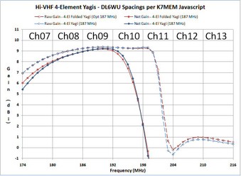
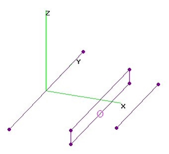
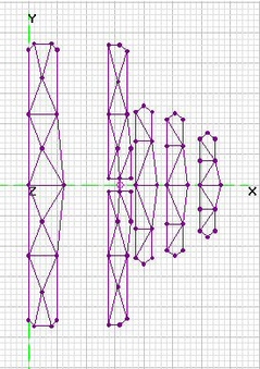
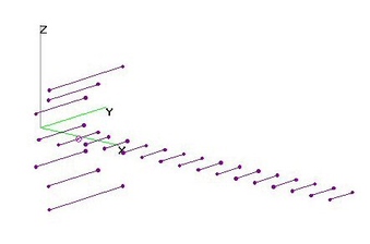
Hi-VHF 4-El K7MEM Yagi: Folded vs Not (30May2009)Hi-VHF 4-Element Yagi Antennas - based on Dave47's antenna, designed per K7MEM (DL6WU) on-line calculator:
http://www.avsforum.com/avs-vb/showthread.php?p=13785312
http://www.avsforum.com/avs-vb/showthread.php?p=16552404
Compares 300-ohm Folded Dipole Yagi (Dave47's) to 75-ohm non-folded Yagi: essentially the same performance.
Same Boom Lengths=58.7-in.
Net Gain only covers Ch8 and Ch9. Raw Gain extends throughout Ch10, but with excessive SWR.
So these 4-Element Yagis have LESS bandwidth than similar 8-Element Yagis.
NEC simulation normally does NOT include the boom. When constructing a real antenna, a "Boom Correction"
is added to the length of each element to compensate for the additional loading from the metal in the boom,
but ONLY when using METAL boom construction.
CLICK ON IMAGE (and click again) TO SEE HIGHER REZ. |
| 10980 Visits
9 Items
Shared Album | |
|
 | 45.
Hi-VHF 5-El FD-Yagi - OPTimized (22 Jun 2019)Hi-VHF 5-Element Folded Dipole Yagi analyzed with 4nec2 after determining Dimensions using
nikiml's Python Optimization Scripts, assuming 3/8-in O.D. Aluminum Tubing and NON-METALLIC Boom.
If using a METAL Boom, a small Boom Correction MAY be Required, see Yagi Album Entry Webpage.
Boom Length = 28.3-in.
Hi-VHF Raw Gain = 7.3 to 8.7 to 8.1 dBi, F/B & F/R Ratio Min = 17.2 dB (GOOD) and SWR (300-ohms) under 2.4. |
| 1587 Visits
13 Items
Shared Album | |
|
 | 46.
Hi-VHF 5-El FLF Yagi - OPTimized (20 July 2019)Hi-VHF 5-Element Flat-Loop-Fed (FLF) Yagi analyzed with 4nec2 after determining Dimensions using
nikiml's Python Optimization Scripts.
Hi-VHF Raw Gain = 7.4 to 10.7 dBi, F/B & F/R Ratio Min = 14.9 dB and SWR (300-ohms) under 2.6. |
| 996 Visits
12 Items
Shared Album | |
|
 | 47.
Hi-VHF 5-El Yagi Optimized by K6STI (June 20, 2009)K6STI's Hi-VHF 5-Element Yagi with Rearward Swept Driver Element analyzed using 4nec2.
4nec2 files are included in *.doc format, providing all dimensions. Save as *.txt format then rename as *.nec.
4nec2 files can also be imported into EZNEC and other antenna simulation programs.
Brian Beezley, K6STI, used his AO 8.06 Antenna Optimizer to find a configuration that minimized response to the rear.
On 19Jun he replaced Original with slightly revised RevA, which has improved SWR and Gain:
http://www.ham-radio.com/k6sti/vhftv.htm
K6STI's Optimized Yagi design is only 31.4-inches long and 32.4-inches wide, but provides good coverage across all Hi-VHF
channels (Ch7-13) with excellent Front-to-Rear (F/R) and Front-to-Back (F/B) Ratios and moderate (7.4-9.3 dBi) Net Gain.
Although slightly longer, performance differences between versions are very small, mostly reflecting fine tuning.
In 4nec2 analyzes, F/R is the ratio of gain towards the front (azimuth = 90-deg) to gain towards the rear (azimuth = 180-deg).
And F/B is ratio of gain exactly towards the front to gain towards the rear with an included angle of (my choice) +/- 45-deg.
This is different than the worst side-lobe level calculated by K6STI. Note that 4nec2 calculated SWR is slightly higher than K6STI's.
I also investigated a Folded Dipole variant which has a Characteristic Impedance of 300 ohms (vice 75-ohm for above).
After optimizing Folded Dipole Element separation, SWR was further reduced to under 1.4 with up to 0.25 dB more gain on
Ch13 than K6STI's Yagi RevA, with small increase in F/R and F/B (except Ch12-13 decreased some). [Further optimization is possible.]
DIYers can consider whether the small mis-match loss of a 1:1 Coax Balun (or direct connect) is smaller (or greater)
than the small (0.5 dB) loss in Hi-VHF band for a low-loss 4:1 Balun, as discussed HERE:
http://www.avsforum.com/avs-vb/showthread.php?p=15851345
http://www.ham-radio.com/k6sti/balun.htm
http://homepage.mac.com/kenwetzel/Low_Loss_Balun.htm
Gain, F/B and F/R are compared to 4-El K7MEM Yagis (only 2-3 channels), 8-El K7MEM Yagis (only 3 channels),
as well as fol. full band antennas: 14-Element ZS6BTE LPDA, 14-El Wedge Zig-Zag LPA and 14-El Stacked Zig-Zag LPA.
All of the 8-El and 14-El antennas are much longer (about 100 inches), with higher gain.
An open challenge is to design a compact HIGH GAIN Hi-VHF antenna with FULL-BAND coverage....
EDIT (20Jun2009 @ 08:10am): Updated charts to reflect comparison of RevA to Original.
EDIT (19Sep2010): Added FORWARD Gain and SWR (75-ohm) charts for UHF Band...although it might pick up strong signals,
it does NOT provide good performance in the UHF Band. |
| 20843 Visits
29 Items
Shared Album | |
|
 | 48.
Hi-VHF 6-El FD-Yagi - OPTimized (23 Apr 2016)Hi-VHF 6-Element Folded Dipole Yagi analyzed with 4nec2 after determining Dimensions using
nikiml's Python Optimization Scripts, assuming 3/8-in O.D. Aluminum Tubing and NON-METALLIC Boom.
If using a METAL Boom, a small Boom Correction is Required, see Yagi Album Entry Webpage.
Boom Length = 60.0-in.
Hi-VHF Raw Gain = 7.9 to 11.2 dBi, F/B & F/R Ratio Min = 17.7 dB (GOOD) and SWR (300-ohms) under 2.4. |
| 4330 Visits
16 Items
Shared Album | |
|
 | 49.
Hi-VHF 7-El FD-Yagi - OPTimized (5 Jul 2016)Hi-VHF 7-Element Folded Dipole Yagi analyzed with 4nec2 after determining Dimensions using
nikiml's Python Optimization Scripts. Width = 34.1-in, BOOMLENGTH = 110-in.
Hi-VHF Raw Gain = 8.5 to 11.3 to 10.7 dbi, F/B & F/R Ratio Min. = 18.3 dB (GOOD) and SWR (300-ohms) under 2.6. |
| 2290 Visits
15 Items
Shared Album | |
|
 | 50.
Hi-VHF 8-El K7MEM Yagi: Folded vs Not (May 27, 2009)Hi-VHF 8-Element Yagi Antennas, using DL6WU Spacings per K7MEM Javascript:
http://www.k7mem.150m.com/Electronic_Notebook/antennas/yagi_vhf.html
Ch8-10 8-El Yagi has 93-in Boom and Ch11-13 8-El Yagi has 85-in Boom.
Following shows performance of two antennas, one optimized for Ch8-10 (190 MHz design frequency)
and the other optimized for Ch11-13 (208 MHz design frequency). Rapid drop in Gain on next lower channel(s)
(e.g. CH7 or Ch10) could cause reception problems. This is due to loss of Raw Gain and ALSO excessive SWR.
The Front-to-Rear Ratio (F/R) was "moderate", rising to "good" only across part of the center channel.
In this respect, these are truly "Single Channel Yagi's" and the design frequency readjusted for best performance.
These results are for quarter inch copper tubing (aka refrigerator plumbing) with a non-metallic boom.
A run with 1-inch O.D. tubing did not help, it severely restricted the bandwidth (not shown).
A 300-ohm input 8-El K7MEM Folded Dipole with 3-in separation between elements was compared to
the "stick" Yagi, showing a significant improvement in SWR, although there was negligible difference in Raw Gain.
The flatter SWR curve illustrates the broader operating bandwidth of the Folded Dipole configuration.
4nec2 antenna simulation files are included below if anyone wants to try different element sizes.
They also list the element lengths and spacings to assist DIY construction.
These 75-ohm antennas need a 1:1 Balun, either of the Choke, 1/4-Wavelength Matching or Transformer variety.
A 300-ohm antenna using a 4:1 Balun can be constructed by substituting a Folded Dipole for the Driven Element.
CONCLUSION: DL6WU type Hi-VHF Yagi's can provide good Gain, but only over a bandwidth of three adjacent Hi-VHF channels.
And Front-to-Rear Ratio drops off away from the center channel. These Gain results are consistent with
Ken Nist's HDTVPrimer NEC Sim results for Wade "Single Channel" 10-Element Yagis:
http://www.hdtvprimer.com/ANTENNAS/WadeSCY.html
Either K6STI's 5-El Yagi, a LPDA (Log Periodic Dipole Array) or Zig-Zag LPA is recommended for DIY Full Band coverage:
http://imageevent.com/holl_ands/zigzaglpa |
| 11933 Visits
26 Items
Shared Album | |
|
 | 51.
Hi-VHF 8-El FD-Yagi - OPTimized (17 May 2015)Hi-VHF 8-Element Folded Dipole Yagi analyzed using 4nec2 after Dimensions were determined
using nikiml's Python Optimization Scripts.
Boomlength = 64.8-inches.
Hi-VHF Raw Gain = 8.9 to 11.4 to 10.2 dBi, F/B & F/R Ratio Min = 19.7 dB (EXCL) and SWR (300-ohms) Under 2.1 |
| 5323 Visits
12 Items
Shared Album | |
|
 | 52.
HiVHF 9-El FD-Yagi - 1 vs 3 Refl. Rods (24 Dec 2015)Hi-VHF 9-Element Folded Dipole Yagi was analyzed, comparing Efficiency
of 1 Reflector Rod versus 3 Reflector Rods with 2 Fewer Directors.
DETAILED ANALYSIS TO BE UPLOADED SOONISH....... |
| 2381 Visits
2 Items
Shared Album | |
|
 | 53.
HiVHF 9-El FD-Yagi, Stellar Labs 30-2475 (14 Dec 2015)Hi-VHF 9-Element Folded Dipole Yagi, including 3 Reflector Rods, MCM Stellar Labs 30-2475,
analyzed using 4nec2. Initial Dimensions were provided by user [MikeBear].
Analysis revealed that Antenna per MikeBear's Measurements were very close to OPTIMUM,
for the chosen use of Three Reflector Rods....but Repurposing Two RR's as Directors improved
Raw Gain on Ch13 by about 1 dB and F/R Ratio improved several dB on Lower Channels.
Several Versions are presented here [For comparison, completely Re-Optimized 9-El FD-Yagi's
are Analyzed in another Album]:
a) Per MikeBear Measurements with Upper/Lower Reflector Rods 2-in in FRONT of Middle Reflector Rod:
HiVHF Raw Gain = 8.7 to 10.8 dBi, F/B & F/R Ratio = 10.3 to 21.0 to 19.2 to 19.8 dB
[Poor on Low Channels] and SWR (300-ohms) is Under 2.2 (EXCELLENT).
Moving the X and/or Z-Coordinates of the two Upper/Lower Reflector Rods in vicinity of current
locations did NOT significantly improve either Gain, SWR or F/R Ratio.
Boom Length = 59.375-in + Ends.
====================================
b) Analyzed Upper/Lower Reflector Rods Repurposed as Two Additional Directors:
[Requires a Front Boom Extension.]
HiVHF Raw Gain = 8.6 to 12.0 dBi, F/B Ratio = 14.1 dB and SWR (300-ohms) Under 2.2.
Improves Ch13 Gain and F/R Ratio on Lower Channels. SWR is Excellent.
New Boom Length = 95.7-in + Ends
c) Upper/Lower Reflector Rods were removed to investigate degradation to F/R Ratio
(at expense of Raw Gain). See below Charts for results.
d) ALL three Reflector Rods were removed to investigate degradation to F/R Ratio
(at expense of Raw Gain). See below Charts for results.
e) Location of Upper/Lower Reflector Rods relative to Middle Reflector was Re-Optimized,
but there was NO overall improvement when Constrained to be BEHIND the Folded Dipole.
====================================
CORRECTION (14 Dec 2015): This 9-El FD Yagi Analysis replaces Earlier Analysis (8-El FD Yagi)
that was MISSING Director just 2.5-in in front of Folding Dipole [very hard to see in mfr diagram].
There was only a few tenths of dB change in Performance with much lower SWR. |
| 7643 Visits
34 Items
Shared Album | |
|
 | 54.
Hi-VHF 10-El FD-Yagi - OPTimized (17 May 2015)Hi-VHF 10-Element Folded Dipole Yagi analyzed using 4nec2 after Dimensions were determined
using nikiml's Python Optimization Scripts.
Boomlength = 98.6-inches.
Hi-VHF Raw Gain = 9.7 to 12.9 to 10.1 dBi, F/B & F/R Ratio Min. = 20.8 dB (EXCL) and SWR (300-ohms) Under 1.7. |
| 3908 Visits
12 Items
Shared Album | |
|
 | 55.
Hi-VHF 10-El FD-Yagi - Lorkoe's Antique (17 Jun 2010)Hi-VHF 10-Element Yagi with Folded Dipole, Rescaled for Hi-VHF Band.
Dimensions by [300ohm] for an (as yet unidentified) Antique Antenna salvaged by [Lorkoe]:
http://lh4.ggpht.com/_xp43tcwB5ps/TBgusuw9whI/AAAAAAAABAA/nij0uopKPJE/s1024/IMG_6731.JPG
Boom Length = 78 inches.
Element Lengths and Spacing (wrt Driven Element #2, in inches):
1) 31.8 -11.6
2) 25.2 0.0
3) 24.2 8.3
4) 23.2 16.6
5) 23.2 24.9
6) 23.0 33.2
7) 23.0 41.5
8) 23.0 49.8
9) 23.0 58.2
10) 23.0 66.4 |
| 11478 Visits
11 Items
Shared Album | |
|
 | 56.
Hi-VHF 12-El FD-Yagi - OPTimized (15 Mar 2013)Hi-VHF 12-Element Folded Dipole Yagi analyzed using 4nec2 after Dimensions were determined
using nikiml's Python Optimization Scripts, with two different assumptions.
Optimized Dimensions are found in each 4nec2 File and may be rounded to nearest 1/8 or 1/4-inch.
Python Optimization Control Script is appended to the end of each 4nec2 File.
a) Hi-VHF 12-El FD-Yagi with 16-in max spacing between Directors.
Target function: (max_ml+8*max_gain_diff+4*max_f2r_diff+max_f2b_diff)
Boom Length = 107 inches.
Hi-VHF Raw Gain = 10.0 to 13.1 dBi
F/B & F/R Ratio Min = 22 dB (EXCELLENT)
SWR (300-ohms) Max = 2.5
FYI: Trying to increase Max Gain at expense of lower F/B & F/R and/or higher SWR,
I tried LARGER max_gain multipliers (e.g 16 & 32). However, this resulted in SWR climbing
to unacceptable levels.
b) Hi-VHF 12-El FD-Yagi with 25-in max spacing between Directors.
Target function: (max_ml+8*max_gain_diff+4*max_f2r_diff+max_f2b_diff)
Boom Length = 138 inches.
Hi-VHF Raw Gain Max = 10.0 to 14.0 dBi
F/B & F/R Ratio Min = 17 dB (GOOD)
SWR (300-ohms) Max = 2.8 |
| 8189 Visits
21 Items
Shared Album | |
|
 | 57.
Hi-VHF 12-El FD-Yagi (3ReflRods) - kgb (13 Mar 2013)Hi-VHF 12-Element Folded Dipole Yagi (3 ReflRods) analyzed using 4nec2.
Boom Length = 98-inches.
Max Raw Gain = 13.3 dBi, Max F/B & F/R Ratios ~ 22 dB, Min = 12.8 dB and SWR Under 2.0. |
| 6392 Visits
11 Items
Shared Album | |
|
 | 58.
HiVHF 13El FD-Yagi - Stellar Labs 302476 (5 May 2019)Hi-VHF 13-Element Folded Dipole Yagi, including 4 Reflector Rods, MCM Stellar Labs 30-2476,
analyzed using 4nec2. Dimensions were provided by user [majortom].
HiVHF Raw Gain = 9.8 to 12.5 dBi, F/B & F/R Ratio = 15 to 25 to 17 dB [Good to Excellent]
and SWR (300-ohms) is Under 2.7 [Excellent].
That is 0.9 to 1.7 dB higher Gain and much better F/B & F/R on low Channels than than S-L 30-2475 9-El FD Yagi. |
| 2633 Visits
15 Items
Shared Album | |
|
 | 59.
Hi-VHF 13-El FD-Yagi (2ReflRods) - kgb (17 Jun 2010)Hi-VHF Optimized 13-Element Folded Dipole Yagi (2 Reflector Rods), RESCALED from
a UHF design posted by kgb, analyzed using 4nec2. Presumes use of Type M Copper Tubing
with O.D.=0.5695-inch.
Boom Length=115.33-in (9.6-ft).
Hi-VHF Raw Gain = 8.3 to 11.3 dBi, F/B & F/R Ratio Min. = 16.5 dB (GOOD) and SWR Under 2.4. |
| 7789 Visits
11 Items
Shared Album | |
|
 | 60.
Hi-VHF 16-El FD-Yagi - OPTimized (2 May 2016)Hi-VHF 16-Element Folded Dipole Yagi analyzed using 4nec2 after Dimensions were determined
using nikiml's Python Optimization Scripts.
Boom Length = 207-inches (17.25-ft).
Raw Gain = 10.4 to 15.5 to 15.4 dBi, F/B & F/R Ratio Min. = 21.6 dB (EXCL) and SWR (300) Under 2.0. |
| 2726 Visits
15 Items
Shared Album | |
|
 | 61.
Hi-VHF 18-El FD-Yagi - OPTimized (30 Apr 2016)Hi-VHF 18-Element Folded Dipole Yagi analyzed using 4nec2 after Dimensions were determined
using nikiml's Python Optimization Scripts.
Boom Length = 206.1-inches (17.2-ft).
Raw Gain = 10.8 to 15.5 to 15.1 dBi, F/B & F/R Ratio Min. = 21.9 dB (EXCL) and SWR (300) Under 1.8. |
| 2357 Visits
15 Items
Shared Album | |
|
 | 62.
Hi-VHF 20-El FD-Yagi - OPTimized (10 May 2015)Hi-VHF 20-Element Folded Dipole Yagi analyzed using 4nec2 after determining Dimensions using
nikiml's Python Optimization Scripts.
Boom Length = 272-inches (22.7-ft).
Hi-VHF Raw Gain = 10.9 to 16.4 to 15.9 dBi, F/B & F/R Ratio Min. = 22.4 dB (EXCL) and SWR (300-ohms) Under 1.7. |
| 2271 Visits
21 Items
Shared Album | |
|
 | 63.
Hi-VHF 22-El FD-Yagi - OPTimized (10 May 2015)Hi-VHF 22-Element Folded Dipole Yagi analyzed using 4nec2 after Dimensions were determined
using nikiml's Python Optimization Scripts.
Boom-Length = 217-in (about 18-ft).
Hi-VHF Raw Gain = 12.5 to 15.2 to 13.9 dBi, F/B & F/R Ratio Min. = 24.0 dB (EXCL) and SWR (300-ohms) Under 2.2. |
| 4554 Visits
12 Items
Shared Album | |
|
 | 64.
Ch13 5-El Yagi - OPTimized by nikiml (4 Sep 2011)Ch13 5-Element Yagi optimized by nikiml analyzed using 4nec2.
Characteristic Impedance is 75-ohms, so a 1:1 Balun should be used.
Although the Gain was maximum on Ch13, the Front-to-Back Ratio was not,
being centered more on Ch12. SWR was excellent, below 2 on Ch13. Boom Length = 48-in.
This antenna is also very usable on Ch11 and Ch12, although the F/B Ratio is fairly small on Ch11.
holl_ands mods to nikiml's 4nec2 file:
1. Added Symbol Rsrc to adjust AGT=1.0 after I found it was a bit off: AGT=0.98 (-0.1 dB).
2. Adjusted Segmentation to agree with AutoSeg(29), since it was somewhat different
(incl. EVEN number segmentation, which AutoSeg never allows).
3. Added my standard set of FR/RP statements, rather than using fat-fingered manual 4nec2 entries. |
| 6693 Visits
11 Items
Shared Album | |
|
 | 65.
Ch13 8-El Yagi - OPTimized by K6STI (19 Sep 2011)Ch13 8-Element Yagi, optimized by K6STI for Gain, SWR and especially Front/Back & Front/Rear Ratios.
Boom Length = 95 inches.
Ch13 Raw Gain=12.9-13.3 dBi. F2R=28.9-33.5 dB. F2B=31.8-41.0 dB.
SWR under 2.56 (w/o shunt cap.) and under 1.19 (with 8.547466 pF shunt capacitor across Feedpoint). |
| 6551 Visits
17 Items
Shared Album | |
|
 | 66.
Ch13 12-El FD-Yagi - OPTimized (15 Mar 2013)Ch13 12-Element Folded Dipole Yagi analyzed using 4nec2.
I calculated dimensions using nikiml's Python Optimization Scripts.
Boom Length=158-in.
Ch13 Raw Gain Max = 14.5 dBi
F/B Ratio more than about 30 dB on Ch13
F/R Ratio more than about 40 dB on Ch13
SWR (300-ohms) Under 1.6 |
| 6986 Visits
12 Items
Shared Album | |
|
 | 67.
Ch12 12-El FD-Yagi - OPTimized (15 Mar 2013)Ch13 12-Element Folded Dipole Yagi analyzed using 4nec2.
I calculated Dimensions using nikiml's Python Optimization Scripts, with two sets of assumptions.
Optimized Dimensions are found in each 4nec2 File and may be rounded to nearest 1/8 or 1/4-inch.
Python Optimization Control Script is appended to the end of each 4nec2 File.
Note that, as expected, allowing Boom Length to grow increases Max Gain, whereas constraining
element-to-element spacing (Delta) would shrink both Max Gain and Boom Length:
a) Ch12 12-El FD-Yagi with 18-in max spacing between Directors.
Target function: (max_ml+64*max_gain_diff+4*max_f2r_diff+max_f2b_diff)
Boom Length = 165 inches.
NOTE: Unusually large multiplier tries to find highest Gain rather than best MismatchLoss, F/R or F/B Ratio.
Higher value in next Yagi STILL wasn't very effective in suppressing MismatchLoss (SWR), F/R & F/R.
Ch12 Raw Gain Max = 14.85 dBi
F/B & F/R Ratio Min = 34 dB on Ch12
SWR (300-ohms) Max = 1.4
b) Ch12 12-El FD-Yagi with 22-in max spacing between Directors.
Target function: (max_ml+128*max_gain_diff+4*max_f2r_diff+max_f2b_diff)
Boom Length = 192 inches.
BTW: Without targets for f2r & f2b, they reduced to 14 dB, with only 0.1 dB Max Gain increase.
Ch12 Raw Gain Max = 15.65 dBi
F/B & F/R Ratio Min = 30 dB on Ch12
SWR (300-ohms) Max = 1.4 |
| 5776 Visits
24 Items
Shared Album | |
|
 | 68.
Ch6 2-El FD-Yagi - OPTimized (5 May 2018)Ch6 2-Element Folded Dipole Yagi analyzed using 4nec2 after determining
"best" Dimensions using nikiml's Python Optimization Scripts.
Center Freq = 85 MHz (1/2-WL = 69.43-inches).
L1=70.52, L2=61.87 Overall Element Lengths
D2 = 25.27 = L1 to L2 Element Spacing
Relem=0.064 = Passive Element Radius [AWG8]
RACT=0.064 = Active Element Radius [AWG8]
FW=2.0 = Separation between Long Folded Dipole Elements
Ch6 (82-88 MHz) Raw Gain = 6.6 to 5.2 dBi, F/B & F/R Min. under 8.7 and SWR (300-ohms) under 2.3. |
| 1544 Visits
12 Items
Shared Album | |
|
 | 69.
Ch6 3-El FD-Yagi - OPTimized (6 May 2018)Ch6 3-Element Folded Dipole Yagi analyzed using 4nec2, after determining
"best" Dimensions using nikiml's Python Optimization Scripts.
Center Freq = 85 MHz (1/2-WL = 69.43-inches).
L1=72.37948, L2=65.54579, L3=59.54659 = Element Lengths
D2=24.109, D3=19.19 = Element Spacings
Relem=0.1875 = Passive Element Radius (3/8-in O.D.)
RACT=0.1875 = Active Element Radius (3/8-in O.D.)
FW=3.0 = Separation between Long Folded Dipole Elements
Ch6 (82-88 MHz) Raw Gain = 6.9 to 7.6 dBi, F/B & F/R Min. under 17.4 dB and SWR (300-ohms) under 2.4. |
| 3975 Visits
12 Items
Shared Album | |
|
 | 70.
Ch7 12-El Yagi from v37bqh (27 June 2009)Ch7 12-Element Yagi by v37bqh (rescaled by va3rr for Ch7) analyzed in 4nec2. Boom Length = 186-in.
Must have been optimized, provides excellent 14-15 dBi Gain & 20-22 dB F/B Ratio across a single channel. |
| 6727 Visits
12 Items
Shared Album | |
|
 | 71.
Ch2-6 Antennacraft Y5-2-6 5-El FD-Yagi (6 Dec 2012)Ch2-6 Antennacraft Y5-2-6 5-Element Folded Dipole Yagi analyzed using 4nec2.
The 4nec2 model was prepared by <300ohm> per his measurements on an actual antenna.
Boom Length=77.5-in. |
| 7696 Visits
11 Items
Shared Album | |
|
 | 72.
Ch3 4-El FD-Yagi - OPTimized (23 Jul 2013)Ch3 (60-66 MHz) 4-Element Folded Dipole Yagi, Optimized with nikiml's Python Scripts, analyzed using 4nec2.
If using a Metal Boom, be sure to calculate Boom Corrections (see "Yagi Antennas" Intro webpage).
a) AWG12 Copper Wire:
On Ch3, Raw Gain = 8.4 to 9.0 dBi, F/B & F/R Minimum = 10.6 dB and SWR (300-ohms) Under 1.6.
Boom Length = 113.6-in x 96-in Wide.
b) Quarter Inch Copper Tubing (QICT) or Braided-Shield in RG-59 Coax (insulation can be left on).
Braided-Shield in RG-59 Coax (insulation does NOT need to be removed) is equivalent to QICT.
On Ch3, Raw Gain = 8.4 to 8.6 dBi, F/B & F/R Minimum = 10.9 dB and SWR (300-ohms) under 1.6.
Note that QICT version is only slightly better than AWG12 version.
Boom Length = 116.8-in x 96-in Wide. |
| 7044 Visits
24 Items
Shared Album | |
|
 | 73.
Ch3 5-El FD-Yagi - OPTimized (25 Jul2013)Ch3 (60-66 MHz) 5-Element Folded-Dipole Yagi, Optimized with nikiml's Python Scripts, analyzed using 4nec2.
If using a Metal Boom, be sure to calculate Boom Corrections (see Yagi Intro webpage).
a) AWG12 Copper Wire:
On Ch3, Raw Gain = 8.8 to 10.0 dBi, F/B & F/R Minimum = 12.4 dB and SWR (300-ohms) Under 2.7.
Boom Length = 136.4-in.
b) Quarter Inch Copper Tubing (QICT) or Braided-Shield in RG-59 Coax (insulation can be left on).
On Ch3, Raw Gain = 9.1 to 10.0 dBi, F/B & F/R Minimum = 13.1 dB and SWR (300-ohms) Under 2.0.
Boom Length = 160.2-in.
Note there is very little difference between QICT and AWG12 versions. |
| 6005 Visits
24 Items
Shared Album | |
|
 | 74.
Ch3 6-El FD-Yagi - OPTimized (23 Jul 2013)Ch3 (60-66 MHz) 6-Element Folded-Dipole Yagi, Optimized with nikiml's Python Scripts, analyzed using 4nec2.
If using a Metal Boom, be sure to calculate Boom Corrections (see Yagi Intro webpage).
a) AWG12 Copper Wire:
On Ch3, Raw Gain = 9.6 to 11.2 on Ch3, F/B & F/R Minimum = 14.0 dB and SWR (300-ohms) Under 1.6.
Boom Length = 205.7-in.
b) Quarter Inch Copper Tubing (QICT) or Braided-Shield in RG-59 Coax (insulation can be left on).
On Ch3, Raw Gain = 9.6 to 11.2, F/B & F/R Minimum = 14.5 dB and SWR (300-ohms) Under 2.2.
Boom Length = 199.7-in.
Note there is very little difference between QICT and AWG12 versions. |
| 6186 Visits
24 Items
Shared Album | |
| |
