 enlarge 84KB, 577x1024 enlarge 84KB, 577x1024
UHF 3-Bay Dipole + 12RR - OPT
3D View
|  enlarge 287KB, 1024x900 enlarge 287KB, 1024x900
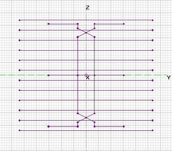
UHF 3-Bay Dipole + 12RR - OPT
Front View
[1 large square = 2.5 inches]
|  enlarge 104KB, 365x1024 enlarge 104KB, 365x1024
UHF 3-Bay Dipole + 12RR - OPT
Top View
[1 large square = 2.5 inches]
|
 enlarge 177KB, 1024x690 enlarge 177KB, 1024x690
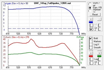
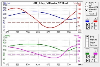
UHF 3-Bay Dipole + 12RR - OPT
UHF Raw Gain = 10.9 to 12.5 dBi
UHF F/B & F/R Ratio Minimum = 17.7 dB
|  enlarge 177KB, 1024x690 enlarge 177KB, 1024x690
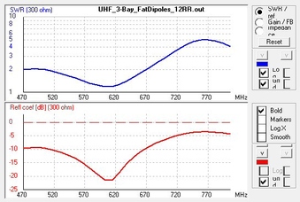
UHF 3-Bay Dipole + 12RR - OPT
UHF SWR (300-ohms) Under 2.7
|  enlarge 216KB, 1024x690 enlarge 216KB, 1024x690
UHF 3-Bay Dipole + 12RR - OPT
UHF Impedance
|
 enlarge 300KB, 1024x1024 enlarge 300KB, 1024x1024
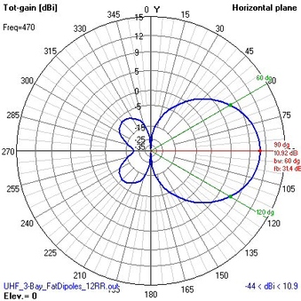
UHF 3-Bay Dipole + 12RR - OPT
Azimuthal Pattern at 470 MHz
|  enlarge 301KB, 1024x1024 enlarge 301KB, 1024x1024
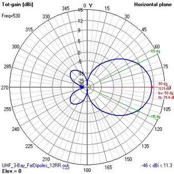
UHF 3-Bay Dipole + 12RR - OPT
Azimuthal Pattern at 530 MHz
|  enlarge 301KB, 1024x1024 enlarge 301KB, 1024x1024
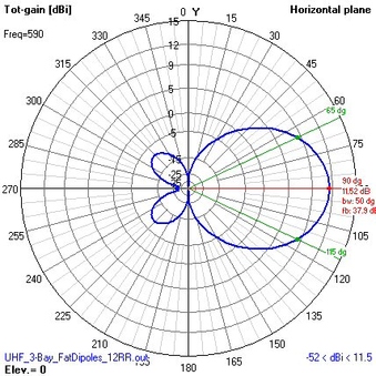
UHF 3-Bay Dipole + 12RR - OPT
Azimuthal Pattern at 590 MHz
|
 enlarge 301KB, 1024x1024 enlarge 301KB, 1024x1024
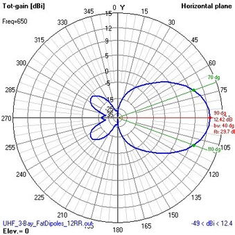
UHF 3-Bay Dipole + 12RR - OPT
Azimuthal Pattern at 650 MHz
|  enlarge 301KB, 1024x1024 enlarge 301KB, 1024x1024
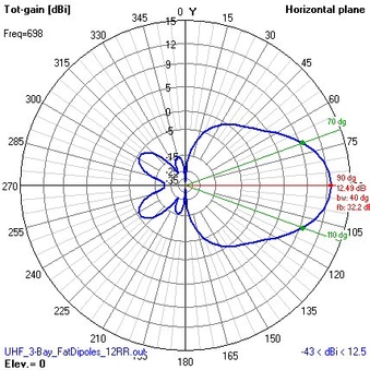
UHF 3-Bay Dipole + 12RR - OPT
Azimuthal Pattern at 698 MHz
|  enlarge 300KB, 1024x1024 enlarge 300KB, 1024x1024
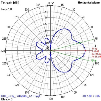
UHF 3-Bay Dipole + 12RR - OPT
Azimuthal Pattern at 798 MHz
|
 enlarge 308KB, 1024x1024 enlarge 308KB, 1024x1024
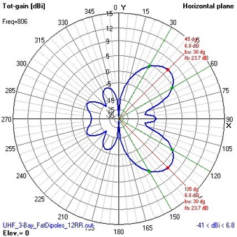
UHF 3-Bay Dipole + 12RR - OPT
Azimuthal Pattern at 806 MHz
|  enlarge 34KB, 791x1024 enlarge 34KB, 791x1024
UHF 3-Bay Dipole + 12RR - OPT
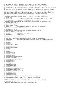
4nec2 File
| 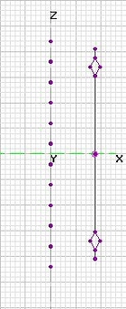 enlarge 118KB, 420x1024 enlarge 118KB, 420x1024
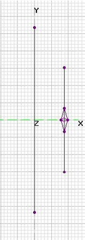
UHF 3-Bay Dipole + 12RR - OPT
Side View
[1 large square = 2.5 inches]
|
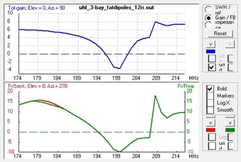 enlarge 175KB, 1024x690 enlarge 175KB, 1024x690
UHF 3-Bay Dipole + 12RR - OPT
Hi-VHF Gain is 6-4 dBi on Ch7-9
and 8 dBi on Ch13, with
more to REAR on Ch10-12
| 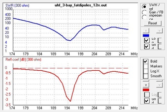 enlarge 202KB, 1024x690 enlarge 202KB, 1024x690
UHF Raw Gain = 10.9 to 12.5 dBi
Hi-VHF SWR (300-ohms) is Excessive
| 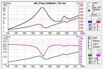 enlarge 222KB, 1024x690 enlarge 222KB, 1024x690
UHF Raw Gain = 10.9 to 12.5 dBi
Hi-VHF Impedance
|
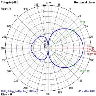 enlarge 302KB, 1024x1024 enlarge 302KB, 1024x1024
UHF 3-Bay Dipole + 12RR - OPT
Azimuthal Pattern at 174 MHz
|  enlarge 303KB, 1024x1024 enlarge 303KB, 1024x1024
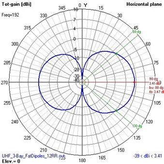
UHF 3-Bay Dipole + 12RR - OPT
Azimuthal Pattern at 192 MHz
|  enlarge 304KB, 1024x1024 enlarge 304KB, 1024x1024
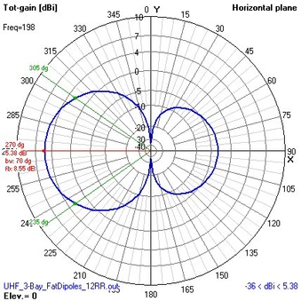
UHF 3-Bay Dipole + 12RR - OPT
Azimuthal Pattern at 198 MHz
|
 enlarge 306KB, 1024x1024 enlarge 306KB, 1024x1024
UHF 3-Bay Dipole + 12RR - OPT
Azimuthal Pattern at 207 MHz
|  enlarge 302KB, 1024x1024 enlarge 302KB, 1024x1024
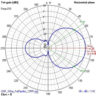
UHF 3-Bay Dipole + 12RR - OPT
Azimuthal Pattern at 210 MHz
|  enlarge 302KB, 1024x1024 enlarge 302KB, 1024x1024
UHF 3-Bay Dipole + 12RR - OPT
Azimuthal Pattern at 216 MHz
|
