 | 1.
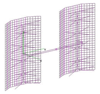
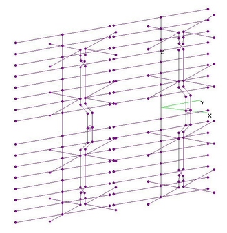
Horiz-Stack 2xFF6 + VDAR + HHH (29 Sep 2015)UHF Horizontally-Stacked 2xFF6's each with Variable Double Angled Reflector (VDAR, 60"Hx36"W)
analyzed using 4nec2 after nikiml's Python Optimumization Scripts determined all 19 Variables.
Summary of Dimensions is found in the below 4nec2 File.
NOTE: 2"Hx2"W Grid Size assumed to fit within constraints of 4nec2. If 1"Hx2"W Grid Size
is used, F/B & F/R Ratios would improve by perhaps 5 dB, as illustrated here:
http://imageevent.com/holl_ands/multibay/8bayrefl/oldcm4228wrefl
UHF Raw Gain = 17.7 to 19.5 to 18.9 to 19.6 dBi, F/B & F/R Ratio Minimum = 14.9 dB and
SWR (300-ohms) Under 2.2. [Raw Gain = 19.0 dBi +/- 0.6 dB, except 17.7 dBi at 470 MHz.]
Hi-VHF Raw Gain = 12.2 to 12.6 to 11.1 dBi, F/B & F/R Ratio Minimum = 13.1 dB and
Hi-VHF SWR (300-ohms) = 10.7 to 26.0 to 13.5 is Excessive. |
| 2482 Visits
22 Images
Gallery Album | |
|
 | 2.
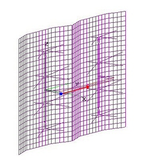
Horiz-Stack 2xFF4 + DAR + HHH (17 Oct 2014)UHF+Hi-VHF HFF8, a Horizontal Stack of 2 ea Free-Form 4-Bays (FF4) with Double Angle Reflectors (DAR)
(each 48" H x 36" W using 2x2-in Grid) and Holl_ands Horizontal Harness (HHH) were analyzed using 4nec2.
Essentially all Dimensions were determined using nikiml's Python Optimization Scripts.
Performance was slightly "Better" at THREE notable Stacking Distances:
34.821-inches (NO GAP, Continuous Reflector), 35-inches (Metal-to-Metal about 1/4-inch)
and 51-inches, which are analyzed below.
There were notable Stacking Distances further out, but none were particularly "Better".
Although the differences are small, Stack Distance = 35-inches was just
a bit "Better", esp. Hi-VHF, than at 51-inches, although the wider Separation may be slightly
"Better" at combating Multipath Fading due to the reduction in Statistical Correlation
between the two Antenna signals. The "NO GAP between Reflector" alternative was worse.
===========================================
a) Horizontal Stacking Distance (4-Bay Center-to-Center) = 34.821 inches (NO GAP between Reflectors).
T.B.D.
===========================================
b) Horizontal Stacking Distance (4-Bay Center-to-Center) = 35-inches (0.18-in GAP between Reflectors).
UHF Raw Gain = 16.9 to 20.1 to 19.8 dBi, F/B & F/R Ratio Min. = 15.7 dB and SWR (300-ohms) under 3.1.
Hi-VHF Raw Gain = 14.3 to 9.6 dBi, F/B & F/R Ratio Min. = 8.5 dB and SWR (300-ohms) = 30.1 to 10.2 is Excessive.
===========================================
c) Horizontal Stacking Distance (4-Bay Center-to-Center) = 51-inches (16.18-in GAP between Reflectors).
UHF Raw Gain = 17.3 to 19.6 to 19.4 dBi, F/B & F/R Ratio Min. = 12.8 dB and SWR (300-ohms) is under 1.7.
Hi-VHF Raw Gain = 10.6 to 9.7 to 11.6 dBi, F/B & F/R Min. = 12.6 dB and SWR (300-ohms) Min. = 10.4 is Excessive. |
| 3471 Visits
42 Images
Gallery Album | |
|
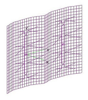 | 3.
Horiz-Stack 2xFF4 + DoubleAng Refl - RFC (3 Jun 2014)UHF+Hi-VHF HFF8, a Horizontal Stack of 2 ea Free-Form 4-Bays (FF4) with Double Angle Reflectors
(each 48" H x 36" W using 2x2-in Grid) were analyzed using 4nec2, presuming they are driven separately.
FF4 dimensions are sameas found for the Optimized version with
a Variable Double Angle Reflector.
Here the usual Horizontal Stacking approach is used, with Equal Length Coax to a (ZERO LOSS) RF Combiner.
Initially, 4nec2 Parameter Sweep plotted Raw Gain versus Horizontal Stacking Distance.
Since SWR plots were always excellent across the UHF Band, they are not shown here.
Performance was slightly "Better" at THREE notable Stacking Distances:
34.821-inches (NO GAP, Continuous Reflector), 35-inches (Metal-to-Metal about 1/4-inch)
and 51-inches, which are analyzed below.
There were notable Stacking Distances further out, but none were particularly "Better".
Although the differences are only a few tenths of a dB, Stack Distance = 51-inches was just
a bit "Better", esp. Hi-VHF, than at 35-inches. The wider Separation may also be slightly
"Better" at combating Multipath Fading due to the reduction in Statistical Correlation
between the two Antenna signals. The "NO GAP between Reflector" alternative was slightly worse.
===========================================
a) Horizontal Stacking Distance (4-Bay Center-to-Center) = 34.821 inches (NO GAP between Reflectors).
UHF Raw Gain = 17.2 to 19.7 dBi, F/B & F/R Ratio Minimum = 16.4 dB & SWR (300-ohms) under 2.1.
Hi-VHF Raw Gain = 10.4 to 9.9 to 10.3 dBi, F/R & F/B Ratio Min = 16.4 dB, although SWR (300-ohms)
under 20 dB is EXCESSIVE, which may or may NOT be an issue in any particular situation.
===========================================
b) Horizontal Stacking Distance (4-Bay Center-to-Center) = 35-inches (0.18-in GAP between Reflectors).
UHF Raw Gain = 17.3 to 20.1 dBi, F/B & F/R Ratio Minimum = 15.8 dB & SWR (300-ohms) under 2.1.
Hi-VHF Raw Gain = 10.5 to 11.7 to 11.9 dBi, F/R Ratio = 11.6 to 14.9 dB, although SWR (300-ohms)
= 24 to 15 dB is EXCESSIVE, which may or may NOT be an issue in any particular situation.
===========================================
c) Horizontal Stacking Distance (4-Bay Center-to-Center) = 51-inches (16.18-in GAP between Reflectors).
UHF Raw Gain = 17.6 to 20.3 dBi, F/B & F/R Ratio Minimum = 14.2 dB and SWR (300-ohms) under 2.1.
Hi-VHF Raw Gain = 13.5 to 11.4 dBi, F/R Ratio = 9 to 19 dB, although SWR (300-ohms) = 29 to 22 dB
is EXCESSIVE, which may or may NOT be an issue in any particular situation. |
| 3597 Visits
69 Images
Gallery Album | |
|
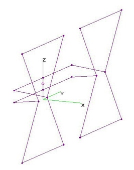
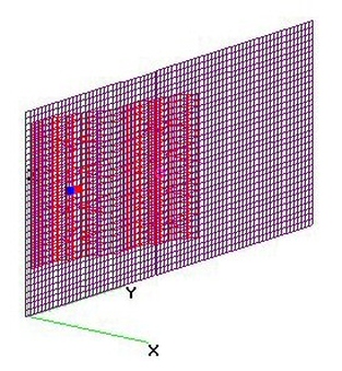 | 4.
Horiz-Stack FF4+DAR Angled Against Wall (9 Aug 2014)Horizontally Stack of Free-Form 4-Bay Bowties (2xFF4) with Double Angled Reflectors (DAR)
analyzed by 4nec2 when Angled Against a Metal Wall.
Three Versions Analyzed:
For fol. Side-By-Side alternatives, cut off 2-in Grid on OUTER (only) side of EACH Reflector and
Bay-to-Bay-Separation = 34.821-in (Reflectors one continous piece) to fit 66-in wide Metal panel.
a) Two Side-By-Side FF4's (DAR=36x34 each), Lossless RF Combiner Mod, to see what is possible:
UHF Raw Gain = 17.3 to 19.3 Along 105-deg Azimuth, F/B & F/R Ratio Min = 15.8 dB
and SWR (300-ohms) under 2.2.
b) Two Side-By-Side FF4's (DAR=36x34 each), HHH (Hollands Horizontal Harness): T.B.D.
For fol. Echelon alternatives, cut off 2-in Grid on either side of EACH Reflector and
Bay-to-Bay-Separation = 32.5-in to fit 66-in wide Metal panel with no "shading" of one
antenna by the other. Note model rotated CCW 15-deg so Pattern points along X-Axis:
c) Two Echelon FF4's (DAR=36x32 each), HHH (Hollands Horizontal Harness):
UHF Raw Gain = 16.6 to 16.4 to 18.3 dBi, F/B & F/R Min = 12.8 dB and SWR (300-ohms) under 2.6. |
| 1960 Visits
36 Images
Gallery Album | |
|
 | 5.
Horiz-Stacked CM4221HD's - RF Combiner (28 Dec 2011)Horizontally Stacked CM4221HD's with RF Combiner analyzed using 4nec2.
Original 4nec2 file from user balm, modified by holl_ands as noted in the file.
NOTE: Charts do NOT include RF Combiner Loss, which is "typically" 0.5 to 1.5+ dB, see:
www.antennahacks.com [Back-To-Back Combiner Loss - divide by two.]
BowLength = 7.9-in, Tine Separation = 3.94-in, Approx. AWG6 wire size (0.157" O.D.).
Inner-Inner Bowtie Spacing = 9.84-in, Outer-Inner Bowtie Spacing = 8.46-in,
Feedline Separation = 1.18-in, with 0.8-in at Crossover (2" from Outer Bowtie), AWG10.
32 Rod Reflectors: 23.6" Long with 1.93" Spacings, O.D.=0.193-in. Separation from Bowties = 4.25-in.
Left to Right Bay Separation = 24.6-in with 1-in Gap between Reflector Rods. |
| 2680 Visits
23 Images
Shared Album | |
|
 | 6.
Horiz-Stck 2xCM4221HD Hacked - NULL BEAM (20 Dec 2013)UHF Horizontally Stacked 2xCM4221HD (Hacked), connected Out-Of-Phase for a NULL on-axis,
with 2 or more Beams on either side, described on HDTVPrimer as the "Two-Antenna Trick":
http://www.hdtvprimer.com/antennas/ganging.html
Since the original CM4221's are no longer available, the replacement CM4221HD was analyzed.
As shown in the charts for five different Horizontal Stacking Distances, a fairly deep Null can
be formed directly on-axis, with Narrow Beams formed on either side of the Null. For some
combinations of Frequency and Stacking Distance, an additional pair of usable Beams may or
may not be formed at angles even further away.
BTW: Horiz. Stacking Distance is between the Centers of each 4-Bay.
Note that for this CM4221HD example (which has a fairly wide Beamwidth), the third pair of
Beams has very little usable Gain. Different Antennas will likely exhibit different performance.
The Chart at the bottom plots the Angle between the forward Null and the Adjacent Beams,
as well as the Secondary Beams (if usable Gain) versus the Horizontal Stacking Distance.
Using CM4221HD's, (without modifications), the Reflector Rods limit how close the 4-Bays
can be mounted. With modifications, the Null-to-Beam Angle could be increased a bit more.
To receive a weak station separated by a very small Angle from a strong local station,
the two Antennas need to have a fairly large Stacking Distance...far more than would be
feasible mounted on a typical Rotator, which is limited in it's ability to tolerate strong
twisting in the wind. If using fixed locations for the two Antennas, their location(s)
would need to be carefully adjusted while monitoring how well the strong local station
is nulled out. In similar Antenna sidelobe nulling adjustments, I had to add a Variable
RF Attenuator to reduce the tuner signals levels closer to threshold to "see" the null.
Per the Azimuthal Pattern Charts, strong signals should be attenuated at least 10-15 dB
relative to the weak desired signal. Actual On-Air tests would need to be conducted
to verify this prediction and see if even deeper Nulls are possible given "real world"
inaccuracies in pointing the Array and matching the Antennas [doublecheck dimensions]. |
| 3862 Visits
76 Images
Shared Album | |
|
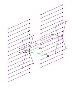
 | 7.
Horiz-Stack UHF Hourglass-Loop - NO Refl (14 Jun 2014)Horizontally Stacked UHF Hourglass-Loops (NO Reflectors) analyzed using 4nec2.
All dimensions were determined using nikiml's Python Optimization Scripts.
An UHF Hourglass-Loop has a VERY WIDE Beamwidth of 80-deg at 470 MHz, decreasing to 70-deg at 698 MHz.
Horizontally Stacked, it drops to 40-deg at 470 MHz, and 30-deg at 698 MHz (to within 10-deg resolution).
Two versions are presented here, the first presumes the use of an RF Combiner attached
to Antenna Feedpoints using Baluns & Equal Length Cables. The second avoids 0.5-1.5+ dB Loss
in RF Combiner by using an Optimized Horizontal Interconnection Harness.
a) RF Combiner: Horizontal Stacking (Center-Center), HD = 16-in provides Max Raw Gain per Optimizer.
UHF Raw Gain = 7.8 to 9.8 to 9.5 dBi and (300-ohms) under 1.9.
=====================================
b) Holl_ands Horizontal Harness (HHH): Interconnection using HHH rather than RF Combiner,
otherwise ALL Dimensions are the SAME as the above Model.
Dimensions of HHH wires were determined using nikiml's Python Optimization Scripts:
HD = 16.0-in = Horizontal Stacking Distance (Center-To-Center).
HD/2 = 8.0-in, Length of Harness wires from Feedpoint to Center of each Hourglass-Loop was per above Model:
Diagonal = 4.0-in, Length from Harness Wires to each Hourglass-Loop Feedpoint.
Hw = 1.43-in (may round to 1.5-in),
Xh = -3.75-in = X-Axis Separation between Harness Wires and Hourglass-Loops.
TOTAL HARNESS WIRE LENGTH (2 required) = 25-in = 2x8.0+2x4.0+2x0.5 (for eyelet)
UHF Raw Gain = 8.6 to 10.1 dBi, F/B and F/R Ratio = 3.5 to 1.8 dB and (300-ohms) under 1.9.
Note that HHH acts somewhat as a REFLECTOR, increasing Raw Gain in the Forward direction,
providing significantly MORE Gain than RF Combiner Model above....and NO LOSS due to Combiner. |
| 1912 Visits
33 Images
Shared Album | |
|
 | 8.
Horiz-Stack UHF Hourglass-Loop + 15RR (11 Jul 2014)UHF Horizontally Stacked Hourglass-Loops with 15 Reflector Rods analyzed using 4nec2
where nikiml's Python Optimization Scripts were used to Optimize dimensions of the
HHH (Hollands Horizontal Harness) and Separation between Hourglass-Loops.
Alternatively, Sidelobes would be minimized with minimum Separation.
Stacking Distance & dimensions of HHH wires determined using nikiml's Python Optimization Scripts:
HD = 29.0-in = Horizontal Stacking Distance (Center-To-Center).
HD/2 = 14.5-in, Length of Harness wires from Feedpoint to Center of each Hourglass-Loop was per above Model:
Diagonal = 4.0-in, Length from Harness Wires to each Hourglass-Loop Feedpoint.
Hw = 1.875-in, Separation between Harness Wires.
Xh = -4.25 = X-Axis Separation between Harness Wires and Hourglass-Loops.
TOTAL HARNESS WIRE LENGTH (2 required) = 25-in = 2x8.0+2x4.0+2x0.5 (for eyelet)
UHF Raw Gain = 12.6 +/- 0.1 dBi is VERY FLAT, F/B & F/R Ratio Min = 16.5 dB
and SWR (300-ohms) under 2.7. |
| 4941 Visits
15 Images
Gallery Album | |
| |