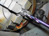
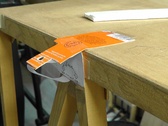
Making the hinges. 1/4" hole to be 1/16" off-center. I measure carefully, then used the lath.
| 
| 
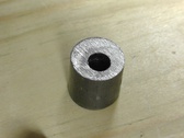
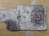
I don't want to spend so much time measuring again and setting up the lath. So, I put a blank in the 5/8" hole.
| 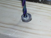
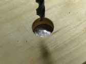
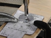
I put the first piece I made on top of it and use a drill bit to make a mark. Then I just take it to the lathe, center the mark, and drill.
|
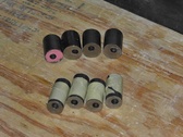
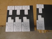
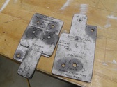
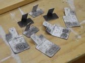
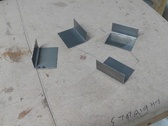
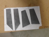
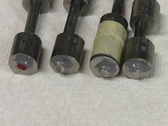
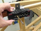
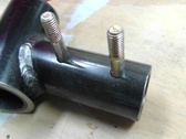
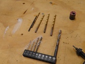
Top four are pieces that get welded to the fitting. Bottom eight (matched pairs) weld to the struts.
| 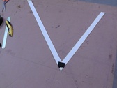
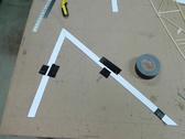
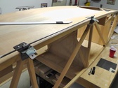
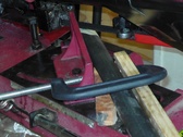
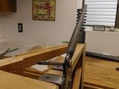
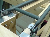
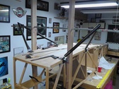
Made a mock-up of gear using plans dimensions.
| 
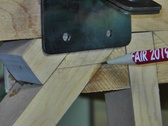
Placed the aft on the correct spot and this is where the forward ended up. Pretty close.
| 
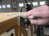
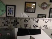
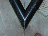
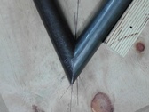
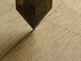
I'm about to measure from the yellow ruler to the tip of the V, where the axle center will be.
|
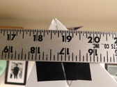
Close to 19". The 1935 plans indicate 17". In 1963 after the Corvair installation, Bernard said 15.5". I'll have to adjust it.
| 
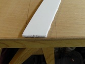
Ready to cut fittings from .080.
| 
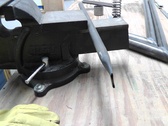
Next I'll file the edges, round the corners and smooth it.
| 
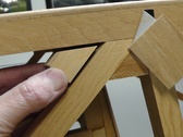
Made mock-up of fitting.
|
Looks like it'll work.
| 
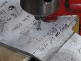
Drilling pilot holes in fittings.
| 
I drilled all the 3/16" holes and the odd 1/4" hole for front left. I will drill the 5/16" holes once the welding is complete. The pilot hole will indicate the location (drilled in the large fitting only).
| 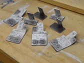
All bent.
|
| 
Half the fittings are bent back. I scanned the drawing and reversed it for those (so I can see the bend line).
| 
They all look good.
| 
Made a small hole to locate the lug location.
|
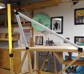
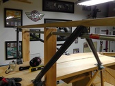
Here's the new gear configuration.
| 
That should work. That's distance to firewall.
| 
Adding blocks where bolt goes through fittings.
| 
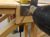
Drilling the 5/16" holes.
|
Will use the fitting to mark the first hole.
| 
A starter hole.
| 
Now to drill straight through.
| 
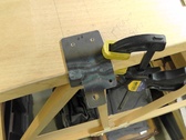
Bolt will hold the fitting in position.
|
All done! Three more to go.
| 
Lining up the holes and positioning the lugs.
| 
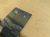
Using JB Weld to hold the position until they are welded.
| 
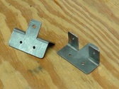
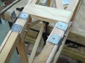
Made the brackets that go on the other side of the ash pieces where the gear fittings attach.
|
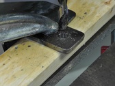
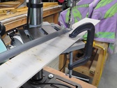
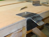
The cut is more than the saw can handle, so I made an adjustment.
| 
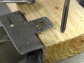
Because the saw cuts from one side only, the gear leg on the left needs to be marked on the bottom. I laid masking tape upside down along a line matching the other legs angle.
| 
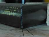
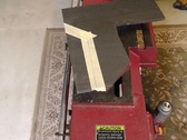
First V done.
| 
|
Now the second.
| 
| 
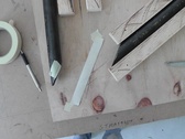
Cutting 1/4" pieces that will connect "V" legs to hinge points.
| 
Done.
|
I am getting hinges ready for welder. A dab of JB Weld on each end will ensure spacing and orientation are maintained.
| 
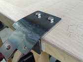
I followed the plans. I should know better. I have to make all four gear fittings again. The side vertical part needs to be longer. The holes are too close to floor board to allow nuts to tighten on the inside bracket. UGH!!!!
| 
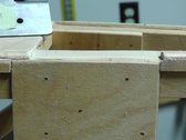
I drew a line to show where the bracket should end. Another 5/16"!
| 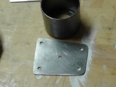
Plate for the upper tail spring attachment.
|
Making the attachment brackets for tailwheel assembly.
| 
Just reamed the 1/4" hole.
| 
Done!
| 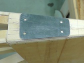
I made a new piece for the upper tail spring attachment. It's larger and holes line up with longeron center.
|
Removed fabric trim for fittings.
| 
Using this guide with a 3/16" to drill straight through.
| 
Finishing with the #11 bit.
| 
|
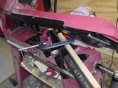
Part of the A frame cooling down.
| 
Drilling the 1/4" hole (using a smaller bit and followed up with reamer)
| 
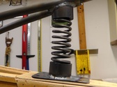
Looks like it'll work. I'm ordering a different spring and will use a different housing.
| 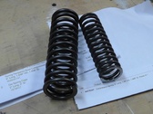
The spring on the left is 2" diameter. Too stiff and big. I bought a 1.5" like on the plans. It's only 5" long, but the tailwheel will add a few more inches.
|
Drilling into the part for the tailwheel.
| 
This will attach to the A frame.
| 
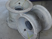
Used rims arrived.
| 
|
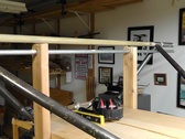
I'm working to merge the A frame into one piece. The tailwheel assembly will attach to that single tube.
| 
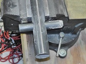
Cutting the cross brace.
| 
That should work.
| 
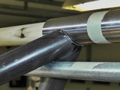
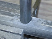
The centerline is between both edges of the pipe.
|
I've checked the pipe is centered and the height is correct along the length.
| 
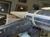
Welding is done, so checking the fit.
| 
Just need to weld.
| 
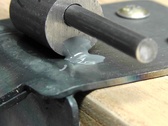
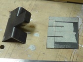
Using these to shape the area of V's for axel location.
|
| 
| 
| 
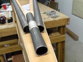
Found a nice straight piece of wood that fit perfectly in the axle's. From Lowes.
|
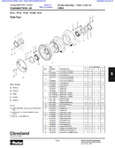
My wheels are 40-24, Column B
| 
Once again making another fitting. But where do i drill the holes?
| 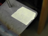
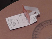
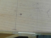
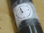
Tape in the area. Place on plane and twist a bolt against tape. Leaves a mark.
| 
Hole centered on the mark made by bolt.
|
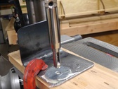
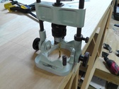
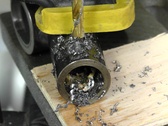
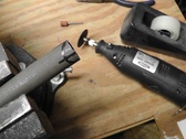
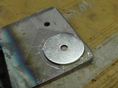
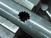
This drill is normally for door hinges. Hole should be dead center.
| 
To make sure the hole doesn't move, I slightly enlarged it with several bits.
| 
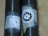
Working on the parts that have bungee cord. I chip away to make the hole.
| 
|
| 
| 
| |
