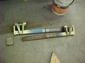
 Here is the jack. It is an older bumper jack style and has quite a bit of lift to it. It has safety locks in the siderails that will hold in case the jack gives way. Hand pump is on an eccentric and has a high release on the back side. Really a nicely build jack. Here is the jack. It is an older bumper jack style and has quite a bit of lift to it. It has safety locks in the siderails that will hold in case the jack gives way. Hand pump is on an eccentric and has a high release on the back side. Really a nicely build jack.
| 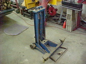 The rails with pads slide out and are adjustable, width wise. Jacks piston was froze and pin sheared off so I took it all apart and pressed the piston out. Cleaned the bore and piston and O ring was fine. Put it all back together and it works fine with no leaks. Kind of happy about that one! The rails with pads slide out and are adjustable, width wise. Jacks piston was froze and pin sheared off so I took it all apart and pressed the piston out. Cleaned the bore and piston and O ring was fine. Put it all back together and it works fine with no leaks. Kind of happy about that one!
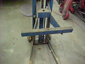
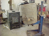
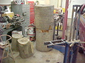
| 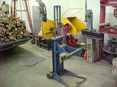 Here is is at full up and it has more than enough reach to get into the boiler.I just have to come up with a holder for the rounds. I want to stand them on the end and then just push them over into the stove. One big round a load will be fine. Here is is at full up and it has more than enough reach to get into the boiler.I just have to come up with a holder for the rounds. I want to stand them on the end and then just push them over into the stove. One big round a load will be fine.
| 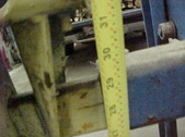 Just a little over 29 inches high as you can see. Just a little over 29 inches high as you can see.
|
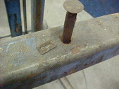 The extendable arms have a pin that keeps them from over extending. One pin and a spring clip is what holds them in. that was easy. The extendable arms have a pin that keeps them from over extending. One pin and a spring clip is what holds them in. that was easy.
|  I'll put these away to use them when I'm back to normal. I'll put these away to use them when I'm back to normal.
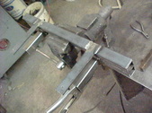
|  My plan is to extend another box beam out to the edge of the feet. That should be more than enough to keep them there. There are no wheels on the from of this so that will have to be addressed too. It was designed to roll in place and let it rest on the floor to jack. I want to roll the weight around. My plan is to extend another box beam out to the edge of the feet. That should be more than enough to keep them there. There are no wheels on the from of this so that will have to be addressed too. It was designed to roll in place and let it rest on the floor to jack. I want to roll the weight around.
| 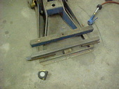 2 thicknesses of 1 1/2" box gets me level. I'll do shorts on the ends so it clears the center bracket. 2 thicknesses of 1 1/2" box gets me level. I'll do shorts on the ends so it clears the center bracket.
|
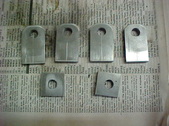 I needed really small, heavy duty casters so I decided to just make them. Easiest spot to mount them was space limited so I just used 3/16 x 1 strap. Drilled the holes and angled the corners. I needed really small, heavy duty casters so I decided to just make them. Easiest spot to mount them was space limited so I just used 3/16 x 1 strap. Drilled the holes and angled the corners.
| 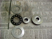 Went to the junk drawer and got some thrust bearings for the swivel. Got some hardened stock for a spacer to go inside to neck it down and make them work nice. Made the spacer about .020 smaller in thickness than the bearing so it'll be smooth. Went to the junk drawer and got some thrust bearings for the swivel. Got some hardened stock for a spacer to go inside to neck it down and make them work nice. Made the spacer about .020 smaller in thickness than the bearing so it'll be smooth.
| 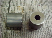 Wheels are hardened tool steel as well, Sometimes keeping junk pays off. i surface ground the ends and made them the same length. Wheels are hardened tool steel as well, Sometimes keeping junk pays off. i surface ground the ends and made them the same length.
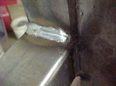
| 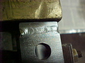 I then TIG welded it all up. I then TIG welded it all up.
|
 Clamped it all in a bench vise for welding. Put the wheel in to keep the size and alignment right. Clamped it all in a bench vise for welding. Put the wheel in to keep the size and alignment right.
|  Repeated the same on the other one. Repeated the same on the other one.
|  I then ground them flat with a 9 inch angle grinder. This is what the bearing washer rides on so it has to be flat to make it work nice. I then ground them flat with a 9 inch angle grinder. This is what the bearing washer rides on so it has to be flat to make it work nice.
| 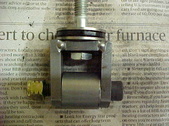 Like I said, they are LOW profile. Doesn't need too much as not really that much weight but I though plastic would give up quick as the jack itself has some girth to it. Like I said, they are LOW profile. Doesn't need too much as not really that much weight but I though plastic would give up quick as the jack itself has some girth to it.
|
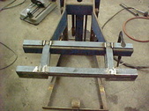
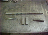 Back to the extension. I started by cutting out all the pieces. I'm going to use box tubing as well for the supports to go back to the original tube. Hopefully my idea will work. Back to the extension. I started by cutting out all the pieces. I'm going to use box tubing as well for the supports to go back to the original tube. Hopefully my idea will work.
|  I started by MIG welding the front feet on. I started by MIG welding the front feet on.
|  MIG welded the inside corners as well. This is 1/8" tubing. MIG welded the inside corners as well. This is 1/8" tubing.
| 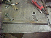 All welded up and ready to try out. All welded up and ready to try out.
|
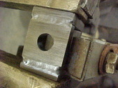
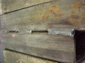
 To attach it, I'm using 3/16" 1 1/2" strap. Plan is to bolt through the original box beam and the downward force will bind it on the lower part of the beam. Basically trapping it in place. I drilled holes in the strap to tap size for the taper headed machine screws. To attach it, I'm using 3/16" 1 1/2" strap. Plan is to bolt through the original box beam and the downward force will bind it on the lower part of the beam. Basically trapping it in place. I drilled holes in the strap to tap size for the taper headed machine screws.
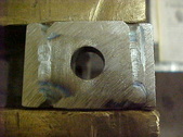
| 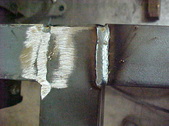 I want everything to slide easy so I filled in the lows with more strap. I then ground the welds smooth to. Here is a before and after. I want everything to slide easy so I filled in the lows with more strap. I then ground the welds smooth to. Here is a before and after.
| 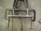 With those in place I clamped it to the jack. I now use the drill press drilled hoes as a guide. Keeps the drill straight, vertically and placement is right so things will line up. With those in place I clamped it to the jack. I now use the drill press drilled hoes as a guide. Keeps the drill straight, vertically and placement is right so things will line up.
| 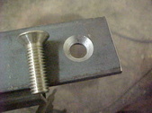 Once they were drilled. I redrilled to size and chamfered the hole. Screw will be basically flush this way. Once they were drilled. I redrilled to size and chamfered the hole. Screw will be basically flush this way.
|
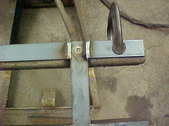 Added more pieces to the back as well so riding surface will be the same. Clamped and welded those in too. These will just lay there so the whole assembly will require just 2 screws to be taken off to remove it. Added more pieces to the back as well so riding surface will be the same. Clamped and welded those in too. These will just lay there so the whole assembly will require just 2 screws to be taken off to remove it.
|  Everything is looking good so far. Everything is looking good so far.
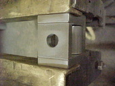
| 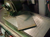 For the caster mounts I'm just putting them in the inside corners at the front of the jack. Got a piece of 3/8" plate and cut it diagonally on the surface grinder. Makes super clean cuts. For the caster mounts I'm just putting them in the inside corners at the front of the jack. Got a piece of 3/8" plate and cut it diagonally on the surface grinder. Makes super clean cuts.
|  Mounting spot is a angled so I'll address that know with another cut. Mounting spot is a angled so I'll address that know with another cut.
|
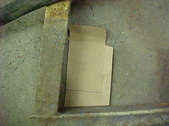 Trusty piece of cardboard works fine. A bevel T square is just as good. Trusty piece of cardboard works fine. A bevel T square is just as good.
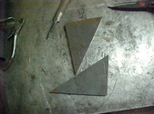
| 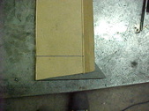 Marked the line and ready to cut. Marked the line and ready to cut.
| 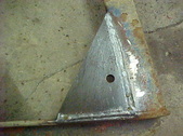 Cut them on the surface grinder as well and then drilled a hole for the caster. Trial fit and welded them home. Cut them on the surface grinder as well and then drilled a hole for the caster. Trial fit and welded them home.
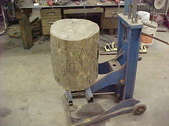
|  For some odd reason, I don't think it's going to fit! If it'll move this around, the normal stuff will be no problem. This one is 26" x 30" Beech For some odd reason, I don't think it's going to fit! If it'll move this around, the normal stuff will be no problem. This one is 26" x 30" Beech
|
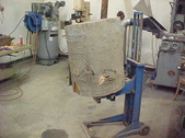 Trial run and it picked a round up fine. Trial run and it picked a round up fine.
|  I put my jack stand back with it's mate. I put my jack stand back with it's mate.
|  This is the normal size. Some of you probably think it is a waste of time but trying to wrestle this one armed would be a chore. Most wood burners and an independent type and I am one of those. Some times you gotta do what you gotta do. This is the normal size. Some of you probably think it is a waste of time but trying to wrestle this one armed would be a chore. Most wood burners and an independent type and I am one of those. Some times you gotta do what you gotta do.
| |
