 I had beefed up the floor and ends with some 1 1/2" Box tubing that was 1/8" thick. With the amount of weight I put on it the original sides had given up. I made these so I can slide in extensions when I'm filling my supply for the Winter. For just feeding the stove I leave the extensions off.Main frame was getting springy and the writing was on the wall. I had beefed up the floor and ends with some 1 1/2" Box tubing that was 1/8" thick. With the amount of weight I put on it the original sides had given up. I made these so I can slide in extensions when I'm filling my supply for the Winter. For just feeding the stove I leave the extensions off.Main frame was getting springy and the writing was on the wall.
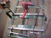
One set of rims were trashed out as the spindles broke from the wheel so some replacements were scrounged. They are now doing the same so some heavier pieces were needed. Getting ready to take off the old gear here.
|  Had a buddy that was junking out a riding lawnmower and asked if I wanted anything. That's what got the ball rolling for this redo and want to keep the cost low. Different sized tires and it will jack up the deck floor but will save leaning over for me, a plus. Had a buddy that was junking out a riding lawnmower and asked if I wanted anything. That's what got the ball rolling for this redo and want to keep the cost low. Different sized tires and it will jack up the deck floor but will save leaning over for me, a plus.
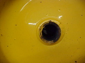
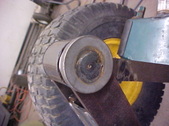
|  Rear wheels have 2 flats in the hub to make the axles "lock" so the can drive the unit. I just want a simple slip so I'll have to get these round. Rear wheels have 2 flats in the hub to make the axles "lock" so the can drive the unit. I just want a simple slip so I'll have to get these round.
|  Set the wheel assembly up in the drill press and drilled them to size. Set the wheel assembly up in the drill press and drilled them to size.
|
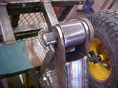
 We're good to go now and it'll accept a 3/4" shaft. We're good to go now and it'll accept a 3/4" shaft.
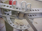
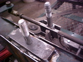
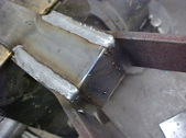
|  Up next is the mounts for the wheel assemblies. I want them to be bolt on so I can use them on something else if needed. I used some 1 3/8" box tubing that is 1/8" thick. This design will tie everything up and spread the load. Just winging the locations and build from there. I drill the box tubing on the drill press then clamp it to the frame as shown here. Keeps the holes straight and true that way. Up next is the mounts for the wheel assemblies. I want them to be bolt on so I can use them on something else if needed. I used some 1 3/8" box tubing that is 1/8" thick. This design will tie everything up and spread the load. Just winging the locations and build from there. I drill the box tubing on the drill press then clamp it to the frame as shown here. Keeps the holes straight and true that way.
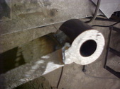
| 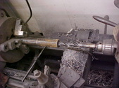 Had a piece of triple wall pipe laying around that will make a nice axle tube. 1/2" wall and just needed a little upsize with a drill. The old lathe took care of that. Had a piece of triple wall pipe laying around that will make a nice axle tube. 1/2" wall and just needed a little upsize with a drill. The old lathe took care of that.
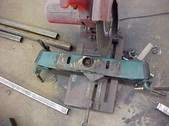
|  For the stands for the axle tube I'm using box tubing. Got the angle needed with a T bevel and transferred the angle to the chop saw. Made them all the same length. For the stands for the axle tube I'm using box tubing. Got the angle needed with a T bevel and transferred the angle to the chop saw. Made them all the same length.
|
 Here is a trick that makes it easier. Instead of trying to tack the uprights on the frame, do it on the bench. I use the straight edge of the table as a guide and measure the needed spread. A couple of small tacks where they join and they will stand up on their own. here you can see both together and the are the same. Here is a trick that makes it easier. Instead of trying to tack the uprights on the frame, do it on the bench. I use the straight edge of the table as a guide and measure the needed spread. A couple of small tacks where they join and they will stand up on their own. here you can see both together and the are the same.
|  After checking everything I tacked them on, then tacked the centered tube. Rechecked and put a few beads to keep it in place, I'll final weld it all up later. After checking everything I tacked them on, then tacked the centered tube. Rechecked and put a few beads to keep it in place, I'll final weld it all up later.
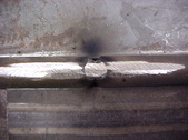
|  Here you can see the original small tack weld and once it's all checked, put on a strength weld. Here you can see the original small tack weld and once it's all checked, put on a strength weld.
|  Since there are no bearings, I gun drilled the axle and tapped it for a grease zerk. I crossed drilled a single hole in the middle so the grease can work out from there. Since there are no bearings, I gun drilled the axle and tapped it for a grease zerk. I crossed drilled a single hole in the middle so the grease can work out from there.
|
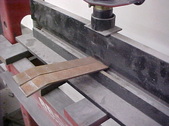
 Decided to make some bent straps to add a little strength where the axle tube meets the box tubing. This bender is great for this type of stuff. Decided to make some bent straps to add a little strength where the axle tube meets the box tubing. This bender is great for this type of stuff.
|  Welded on and it's not going anywhere now. Welded on and it's not going anywhere now.
|  Next is narrowing the front axle. want the tires on the front and back to have the same outside width so 9 inches has to be removed. Chop saw will make this quick and easy. Next is narrowing the front axle. want the tires on the front and back to have the same outside width so 9 inches has to be removed. Chop saw will make this quick and easy.
|  Cleaned up the cuts and ready to weld back together. Cleaned up the cuts and ready to weld back together.
|
 Back as one now and I'll mock it on to see what I need for risers to make it sit level. Back as one now and I'll mock it on to see what I need for risers to make it sit level.
|  This is how I get my measurements. I measure up from the floor on the rear tires and raised the front to the same measurement. Got the distance between the frame and front axle box tube and cut some spacers. Tacked on and checked okay so I'll build from here. This is how I get my measurements. I measure up from the floor on the rear tires and raised the front to the same measurement. Got the distance between the frame and front axle box tube and cut some spacers. Tacked on and checked okay so I'll build from here.
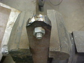
|  With the axle tacked up, the steering was next. Need a wagon, center style system so I cut the head off a 1/2" bolt. Drove it in about 3/4 of the way and welded it. Then ground flush. With the axle tacked up, the steering was next. Need a wagon, center style system so I cut the head off a 1/2" bolt. Drove it in about 3/4 of the way and welded it. Then ground flush.
|  Keeping it centered with the spindles and in the center of the arms is important. This will prevent binding when using. Once checked it was tacked on. Keeping it centered with the spindles and in the center of the arms is important. This will prevent binding when using. Once checked it was tacked on.
|
 Steering rod was cut to length and ready to weld up. This is the way I do them and not the only way. 2 pieces of steel will keep the straight and I grind the ends like a blunt pencil, then tack. Steering rod was cut to length and ready to weld up. This is the way I do them and not the only way. 2 pieces of steel will keep the straight and I grind the ends like a blunt pencil, then tack.
|  Grind flush with an angle grinder and rotate. repeat till done all the way around. You'll see why later. Grind flush with an angle grinder and rotate. repeat till done all the way around. You'll see why later.
| 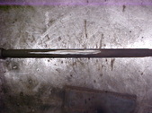 Rod as one again and straight. Rod as one again and straight.
|  I then grind another 1/2" bolts head flush to the body and lay a couple of pieces of steel on both sides. Then clamp with Vise grips and do the aligning. Again, VERY critical to get everything centered and straight so the pivots work in unison. I then grind another 1/2" bolts head flush to the body and lay a couple of pieces of steel on both sides. Then clamp with Vise grips and do the aligning. Again, VERY critical to get everything centered and straight so the pivots work in unison.
|
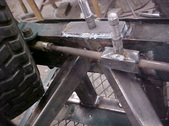 Now that the steering is squared away I slid the wheels on. Used the box tubing to make some angle braces and checked for clearance around the tires and linkage. took awhile to get the angles right. Now that the steering is squared away I slid the wheels on. Used the box tubing to make some angle braces and checked for clearance around the tires and linkage. took awhile to get the angles right.
|  This should keep it in position if I decide to use it as a tow wagon. With the axle lift you have to do something or eventually it'll fail. Pretty stout now. This should keep it in position if I decide to use it as a tow wagon. With the axle lift you have to do something or eventually it'll fail. Pretty stout now.
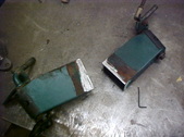
|  With both assemblies welded to a flat surface that bolts on, they can be used for other things in the future if need be. I've learned over the years that needs change and it's nice to have options! With both assemblies welded to a flat surface that bolts on, they can be used for other things in the future if need be. I've learned over the years that needs change and it's nice to have options!
|  Used the same triple wall pipe for a swivel mount for the pull bar/steering. Plan is to make 2 bars. One with a hand pull handle and one with a hitch so you can pull it with a lawn tractor or atv. Gouged the bar and welded it. Then ground the sides flush so the handle won't catch. Used the same triple wall pipe for a swivel mount for the pull bar/steering. Plan is to make 2 bars. One with a hand pull handle and one with a hitch so you can pull it with a lawn tractor or atv. Gouged the bar and welded it. Then ground the sides flush so the handle won't catch.
|
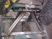
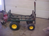
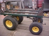 Slid all the wheels on and flip it over to get a look see. Looks like something now and should be able to handle the weight I put on it better. Being higher is a plus for me as it means less bending over. Slid all the wheels on and flip it over to get a look see. Looks like something now and should be able to handle the weight I put on it better. Being higher is a plus for me as it means less bending over.
|  For the hand pull handle I drilled a couple holes in some equal length strap steel. Roughed the rounded ends in with an angle grinder. Bolting them together means they will be the same plus it's easier to keep the edges square. For the hand pull handle I drilled a couple holes in some equal length strap steel. Roughed the rounded ends in with an angle grinder. Bolting them together means they will be the same plus it's easier to keep the edges square.
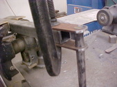
| 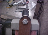 Mounted the belt sander upside down in the vise and smoothed the edges. Saves the hands from pokes. Mounted the belt sander upside down in the vise and smoothed the edges. Saves the hands from pokes.
|  Cut 2 pieces of strap the same length. Bending both of the offsets for the handle at the same time to keep them the same. Cut 2 pieces of strap the same length. Bending both of the offsets for the handle at the same time to keep them the same.
|
 Did the other end the same and welded it on with the pull in place. Did the other end the same and welded it on with the pull in place.
|  Drilled and tapped a stainless 3/4" shaft for the pull. All done here. Drilled and tapped a stainless 3/4" shaft for the pull. All done here.
|  For the other end I cut 6 pieces of strap the same and drilled them. $ will be for the pivots and the other 2 will be for the hitching point. For the other end I cut 6 pieces of strap the same and drilled them. $ will be for the pivots and the other 2 will be for the hitching point.
|  With those all welded on I made a pin fro the handle and hitch attachment. Welded a heavy washer on one end. With those all welded on I made a pin fro the handle and hitch attachment. Welded a heavy washer on one end.
|
 On the other side I drilled it and used a lynch pin for quick and east changes. On the other side I drilled it and used a lynch pin for quick and east changes.
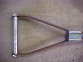
|  Here it is with the pull handle on. I have extension racks for it as mentioned earlier. Here it is with the pull handle on. I have extension racks for it as mentioned earlier.
| 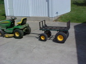 Hooked it up the the little Deere. It should be able to handle the weight now with ease. Hooked it up the the little Deere. It should be able to handle the weight now with ease.
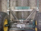
| 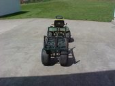 Looks like a Pro street hot rod from the back but it'll help with weight distribution. I'll tear it all down now and smooth up the stuff. Then give it a quick coat of paint. I'll post it with a load on it then. Normally get close to a 1/4 cord on it when pulling it on concrete by hand. Looks like a Pro street hot rod from the back but it'll help with weight distribution. I'll tear it all down now and smooth up the stuff. Then give it a quick coat of paint. I'll post it with a load on it then. Normally get close to a 1/4 cord on it when pulling it on concrete by hand.
|
