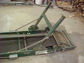
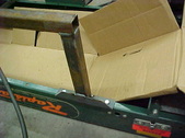
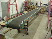
 Got this conveyor off craigslist and it was listed by the manager of a closing Kmart store. It's 20 foot long and has a 2 ft wide with a 18 inch wide belt. Got this conveyor off craigslist and it was listed by the manager of a closing Kmart store. It's 20 foot long and has a 2 ft wide with a 18 inch wide belt.
| 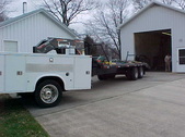 Just home here and backing it in to the shop. Luckily they loaded it with their forklift and helped getting it down to the floor. WE took rollers along to roll out then he again lifted it onto the trailer. Sure made it easy and glad they were so helpful. Just home here and backing it in to the shop. Luckily they loaded it with their forklift and helped getting it down to the floor. WE took rollers along to roll out then he again lifted it onto the trailer. Sure made it easy and glad they were so helpful.
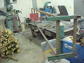
| 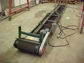 They were using it to feed their storage loft and I bet many a box went up there. It has a 3/4 horse single phase motor with gear reduction. They were using it to feed their storage loft and I bet many a box went up there. It has a 3/4 horse single phase motor with gear reduction.
|  A great feature it has is forward and reverse. I'll be using this flat a lot to load and unload but want to see how it will do loading into a trailer. No paddles or hooks will limit the steepness it can go but the belt is pretty rough and "grippy" so we'll see. A great feature it has is forward and reverse. I'll be using this flat a lot to load and unload but want to see how it will do loading into a trailer. No paddles or hooks will limit the steepness it can go but the belt is pretty rough and "grippy" so we'll see.
|
 It has switches at top and bottom which is great as well. Outside out of reach of an outlet I'll have to take a generator along but it won't be a problem for me. Being able to switch on and off and reverse directions more than makes up for it. It has switches at top and bottom which is great as well. Outside out of reach of an outlet I'll have to take a generator along but it won't be a problem for me. Being able to switch on and off and reverse directions more than makes up for it.
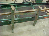
|  My idea is to make a straight substructure so I can have a slide rollers to raise and lower it like a hay elevator. First step is to take off the feet that are on it.m It's all bolted on so it will be easy. My idea is to make a straight substructure so I can have a slide rollers to raise and lower it like a hay elevator. First step is to take off the feet that are on it.m It's all bolted on so it will be easy.
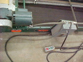
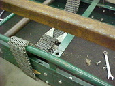
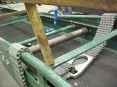
| 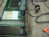 Took the cover off and got a surprise. Twine , plastic and tape was wrapped around the shaft. Then I notice something else. See how the chain is straight? Took the cover off and got a surprise. Twine , plastic and tape was wrapped around the shaft. Then I notice something else. See how the chain is straight?
| 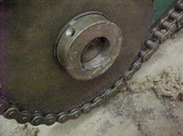 Either someone at the factory or whoever assembled this put the gear on backward. Notice the set screw can't even be tightened as it's on 2/3 on the shaft.It was loose and the only thing from keeping it on was the binding of the chain. Either someone at the factory or whoever assembled this put the gear on backward. Notice the set screw can't even be tightened as it's on 2/3 on the shaft.It was loose and the only thing from keeping it on was the binding of the chain.
|
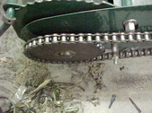 I think they did it because you have to have a long allen wrench to get in there if you put it on right. Notice all the stuff that was wrapped up in it on the floor. I think they did it because you have to have a long allen wrench to get in there if you put it on right. Notice all the stuff that was wrapped up in it on the floor.
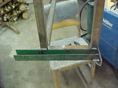
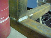
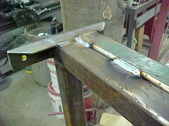
| 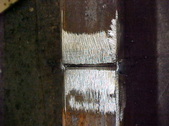 Using Box tubing for the substructure and needed to lengthen the pieces I had. Cleaned them up and put a chamfer so good weld build and strength. Using Box tubing for the substructure and needed to lengthen the pieces I had. Cleaned them up and put a chamfer so good weld build and strength.
| 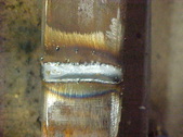 Makes for a good weld and I'll hit all sides. Makes for a good weld and I'll hit all sides.
|  Made up some brackets to bolt it all on. I don't want to weld it on as I can change stuff that way. Rails have holes allready in it so it's a no brainer. Made up some brackets to bolt it all on. I don't want to weld it on as I can change stuff that way. Rails have holes allready in it so it's a no brainer.
|
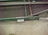
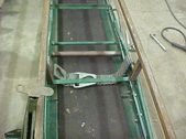
 Welded the ends on at the table then bolted the brackets on and brought the rail over. I then tacked the rail to the brackets. Takes all the measuring out of it and saves mistakes. I put cardbord over the belt to save it from the sparks and such. Welded the ends on at the table then bolted the brackets on and brought the rail over. I then tacked the rail to the brackets. Takes all the measuring out of it and saves mistakes. I put cardbord over the belt to save it from the sparks and such.
| 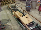 The rails are this tall to get over the motor and gearbox on the other end. They also have a stretcher in the middle and want to leave that on. The rails are this tall to get over the motor and gearbox on the other end. They also have a stretcher in the middle and want to leave that on.
| 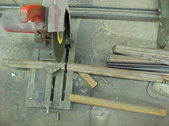 Up next are the cross members that will give it strength and will keep everything square. I'm using a chop saw for the majority of this. Up next are the cross members that will give it strength and will keep everything square. I'm using a chop saw for the majority of this.
| 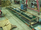 Tacked them all in and kept checking squareness. Everything came together nice. Tacked them all in and kept checking squareness. Everything came together nice.
|
 The center has this tube brace and I want to leave it in. The easiest thing I can think up is an angle tube coming from the cross brace. Not much support under it but I think it'll be fine. Time will tell. The center has this tube brace and I want to leave it in. The easiest thing I can think up is an angle tube coming from the cross brace. Not much support under it but I think it'll be fine. Time will tell.
|  Easiest way I have found is to use a paint stick for a pattern. Trim the angles till their right and the length as well. Takes a little time but saves mistakes and wasted metal. Easiest way I have found is to use a paint stick for a pattern. Trim the angles till their right and the length as well. Takes a little time but saves mistakes and wasted metal.
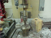
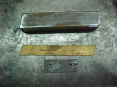
| 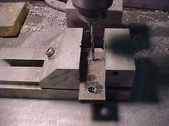 Going to run a bolt up from the bottom to secure it. Got a piece of scrap 3/8" metal and marked the center and in measure of the hole. Centered it and pilot drill. Going to run a bolt up from the bottom to secure it. Got a piece of scrap 3/8" metal and marked the center and in measure of the hole. Centered it and pilot drill.
|  Drill the hole to tap size. Drill the hole to tap size.
|
 Then put a tap in and start it. I keep them loose and then finish by hand. Then put a tap in and start it. I keep them loose and then finish by hand.
|  All tapped and tube cut to size. Now I'll cut the tapped plug to size. All tapped and tube cut to size. Now I'll cut the tapped plug to size.
|  Beveled the edges and set it flush, Tacked it in place. Beveled the edges and set it flush, Tacked it in place.
| 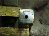 After welding it in I ground the weld to flush. After welding it in I ground the weld to flush.
|
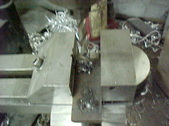
 Both of them done and in and gives a pretty clean look. Both of them done and in and gives a pretty clean look.
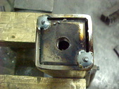
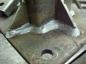
|  On the end I want to have heavy caster wheels so when loading/unloading on the level it doesn't get tippy and it will be self contained. I'm going to reuse the foot bracket as it has adjustment capability. On the end I want to have heavy caster wheels so when loading/unloading on the level it doesn't get tippy and it will be self contained. I'm going to reuse the foot bracket as it has adjustment capability.
|  I cut the feet off and will be mounting it backwards from what they had. Just works out better for my application. Welding it on here. I cut the feet off and will be mounting it backwards from what they had. Just works out better for my application. Welding it on here.
|  Both of them on and doing all the final welding. Both of them on and doing all the final welding.
|
 With the box tubing you can get pretty strong joints because of the surface area. With the box tubing you can get pretty strong joints because of the surface area.
|  Frame work serves double duty to strengthen the whole thing and give me a nice track for the lift wheels to follow. Frame work serves double duty to strengthen the whole thing and give me a nice track for the lift wheels to follow.
| 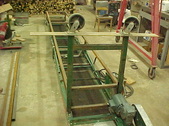 Bolted it all back on and the highest the wheels will be is 54 inches. Bolted it all back on and the highest the wheels will be is 54 inches.
|  The lowest is 36 inches which is about as low as I want to reach. I like this system as I can take the adjustable section out if I want to use it as an elevator or go into a trailer. The lowest is 36 inches which is about as low as I want to reach. I like this system as I can take the adjustable section out if I want to use it as an elevator or go into a trailer.
|
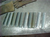
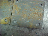
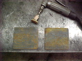 Cut the mounting plates out with the chop saw, rounded the corners and smoothed the edges. Cut the mounting plates out with the chop saw, rounded the corners and smoothed the edges.
| 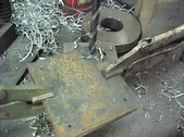 Laid the caster on and traced the holes. center punched and pilot drilled and then drilled the final hole size. Notice I clamped both of them together for time savings. Laid the caster on and traced the holes. center punched and pilot drilled and then drilled the final hole size. Notice I clamped both of them together for time savings.
|  All done and ready to weld onto the legs. All done and ready to weld onto the legs.
| 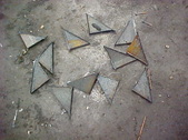 Remember the brackets that attached the box beam rails to the conveyor? I cut 45's on the edges and these are the scraps. Now to use them for strengthening gussets. Remember the brackets that attached the box beam rails to the conveyor? I cut 45's on the edges and these are the scraps. Now to use them for strengthening gussets.
|
 Tacked the brackets on and rechecked them for straightness. Then put the gussets on and welded everything up. Tacked the brackets on and rechecked them for straightness. Then put the gussets on and welded everything up.
|  Makes for a nice strong mounting base. Makes for a nice strong mounting base.
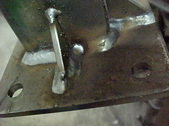
| 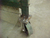 Close up of the front leg. I'll drill a hole through both legs and put a bolt in for now. probably put a pin with linchpin later. Single bolt you see here is one of 2 pinch bolts that Have slide inside. Not strong enough to hold it for me. Close up of the front leg. I'll drill a hole through both legs and put a bolt in for now. probably put a pin with linchpin later. Single bolt you see here is one of 2 pinch bolts that Have slide inside. Not strong enough to hold it for me.
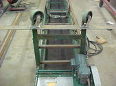
|  Slid the caster assembly in and rolled the conveyor back over. Starting to come together now. Slid the caster assembly in and rolled the conveyor back over. Starting to come together now.
|
