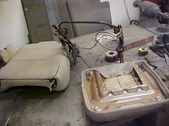
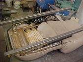
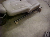
 My Buddy Ed scraps cars all the time so I ask him to let me know when he had one with bucket seats. I needed a scissor jack as well for what I have planned. This one came out of a Toyota. My Buddy Ed scraps cars all the time so I ask him to let me know when he had one with bucket seats. I needed a scissor jack as well for what I have planned. This one came out of a Toyota.
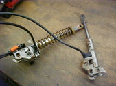
| 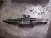 The jack came from the same car and I'll save it for later till I get the framework done. I'll have to keep in mind a design plan for where to mount it. The jack came from the same car and I'll save it for later till I get the framework done. I'll have to keep in mind a design plan for where to mount it.
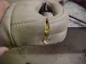
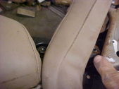
| 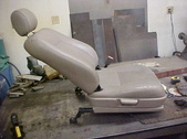 First problem is that the seat doesn't lay all the way down. If you want to make something similar, look for one that does as it will save you some work. This is as far down as it will go from the factory. First problem is that the seat doesn't lay all the way down. If you want to make something similar, look for one that does as it will save you some work. This is as far down as it will go from the factory.
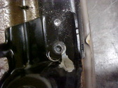
| 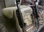 Took off the side trim for now and won't need the position locks so we need to get that limiting factor gone. Took off the side trim for now and won't need the position locks so we need to get that limiting factor gone.
|
 Pretty easy to get all that out but the frame itself hits so the metal will have to be trimmed up. Pretty easy to get all that out but the frame itself hits so the metal will have to be trimmed up.
|  You can make it easier by taking the cushions off. You can make it easier by taking the cushions off.
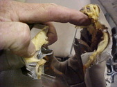
|  The seat base will need this hole cut through. I cut the fabric and foam to get to the metal. The seat base will need this hole cut through. I cut the fabric and foam to get to the metal.
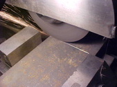
|  Push it to the sides and cut the metal out. I used a angle grinder but a recipricating saw would do it as well. Push it to the sides and cut the metal out. I used a angle grinder but a recipricating saw would do it as well.
|
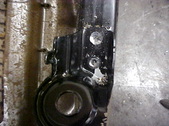
 These are the back locks and spring that are not needed. These are the back locks and spring that are not needed.
|  My thumb is pointing to the metal on the upright that needs to be trimmed off. This is where the limiter/lock attached to. My thumb is pointing to the metal on the upright that needs to be trimmed off. This is where the limiter/lock attached to.
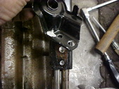
| 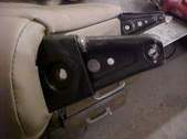 Starting to cut these off here. Won't hurt anything as the strength is still in the seat back. Starting to cut these off here. Won't hurt anything as the strength is still in the seat back.
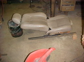
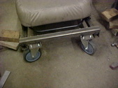
|  Now it lays enough back. Any more and it is uncomfortable. I'll now take the track mounts off the rails so I have a flat surface to work from. Now it lays enough back. Any more and it is uncomfortable. I'll now take the track mounts off the rails so I have a flat surface to work from.
|
 They are riveted and spot welded on. I want to keep the sliders adjustment available for fine tuning in the design if needed. I'll drill the rivets and surface drill the spot welds. They are riveted and spot welded on. I want to keep the sliders adjustment available for fine tuning in the design if needed. I'll drill the rivets and surface drill the spot welds.
|  The fronts are a little bigger. Most all seats have straight runs for the rails so it makes reusing the seats for other stuff nice. The fronts are a little bigger. Most all seats have straight runs for the rails so it makes reusing the seats for other stuff nice.
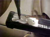
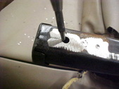
|  I centerpunched the rivets and welds and then just stairstepped a bigger sized drill bit. Just went deep enough on the spot welds to barely go into the base rail. I centerpunched the rivets and welds and then just stairstepped a bigger sized drill bit. Just went deep enough on the spot welds to barely go into the base rail.
|  I pop the rivet head off and pry up to break the spot weld. Rivet head is off on the lower and the spot it about to break free here. I pop the rivet head off and pry up to break the spot weld. Rivet head is off on the lower and the spot it about to break free here.
|
 One tap with a hammer and it's off. One tap with a hammer and it's off.
|  I'll just punch out the remaining rivet on the left and use it as a mounting hole. I'll just punch out the remaining rivet on the left and use it as a mounting hole.
|  Automatic center punch will work fine. Automatic center punch will work fine.
|  Quick and easy hole. Quick and easy hole.
|
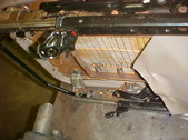
 I slid a standard 1/4 inch bolt through. The head will clear the track fine. I slid a standard 1/4 inch bolt through. The head will clear the track fine.
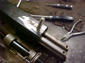
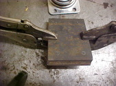
|  Did some measuring and drilled a single hole in 2 pieces of box tubing. I'll now mount them on. Did some measuring and drilled a single hole in 2 pieces of box tubing. I'll now mount them on.
|  With this done I can mark the other holes need by tracing the existing holes. No mismeasures that way. A lot quicker to. With this done I can mark the other holes need by tracing the existing holes. No mismeasures that way. A lot quicker to.
|  Seeing the trace, I just center punch for drilling. Seeing the trace, I just center punch for drilling.
|
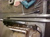
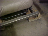
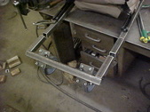
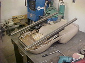 Now the holes line up fine and I have a strong mounting frame to work from. Now the holes line up fine and I have a strong mounting frame to work from.
|  I want it as low as possible and I'll have to angle it some to do that. I blocked up the front and laid down on it till it was what I wanted. This is what I'll go off of. I want it as low as possible and I'll have to angle it some to do that. I blocked up the front and laid down on it till it was what I wanted. This is what I'll go off of.
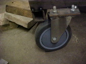
|  Had some bigger casters I pickup up at a yard sale. These do have bearings in them so they will be smooth. If you're going low budget, you can probably get a throw away stroller if you watch curbsides. Need a little more height so I'll move everything up using some 3/4" blocks. It'll just keep anything from dragging on uneven surfaces. Had some bigger casters I pickup up at a yard sale. These do have bearings in them so they will be smooth. If you're going low budget, you can probably get a throw away stroller if you watch curbsides. Need a little more height so I'll move everything up using some 3/4" blocks. It'll just keep anything from dragging on uneven surfaces.
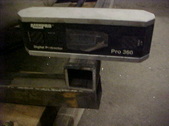
|  Using a digital protractor, it says it is a 6 degree angle. Now time to make the caster mounts. Using a digital protractor, it says it is a 6 degree angle. Now time to make the caster mounts.
|
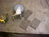
 Got some flat stock and cut the to size on the surface grinder. I'll need 4 of them. Got some flat stock and cut the to size on the surface grinder. I'll need 4 of them.
|  Once all cut, I trace one from the caster and mark the holes. Clamp them all together and drill them all at once. Once all cut, I trace one from the caster and mark the holes. Clamp them all together and drill them all at once.
|  Quick and easy. Quick and easy.
|  Cut another piece of square tubing for a crossmember/caster mount. Cut another piece of square tubing for a crossmember/caster mount.
|
 Used the digital protractor and tacked the box at zero degrees. Got lucky as this height was real close with the caster plate under it so I'll go with it. I'll just fill in the gap with weld when it comes time. Used the digital protractor and tacked the box at zero degrees. Got lucky as this height was real close with the caster plate under it so I'll go with it. I'll just fill in the gap with weld when it comes time.
|  Caster clears the box at this position so it's a go for tacking on. Caster clears the box at this position so it's a go for tacking on.
|  Front is ready so no the back is next. Front is ready so no the back is next.
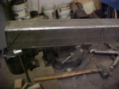
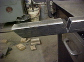
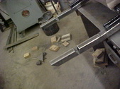
|  I want another flat section to mount the jack so where the rails extend I marked it. Did the math and got what 6 degrees would be in 1.25 inches and marked another line. I'll V cut between the lines leaving the bottom uncut. Gives me another reference point too. Just used a hacksaw. I want another flat section to mount the jack so where the rails extend I marked it. Did the math and got what 6 degrees would be in 1.25 inches and marked another line. I'll V cut between the lines leaving the bottom uncut. Gives me another reference point too. Just used a hacksaw.
|
 Figured how much of a kick up I needed for the back casters while they were mounted to another crossmember I cut. Used the protractor again and got the angles needed. Marked them out and will cut with a hacksaw again. Figured how much of a kick up I needed for the back casters while they were mounted to another crossmember I cut. Used the protractor again and got the angles needed. Marked them out and will cut with a hacksaw again.
|  One side done. One side done.
|  With both sides cut I can tack the crossmember and casters on. You can see the other kick up has been welded on the top. With both sides cut I can tack the crossmember and casters on. You can see the other kick up has been welded on the top.
|  With this tacked on, I'll put it on the floor and it should bend easily to close the gap in the pie cuts. With this tacked on, I'll put it on the floor and it should bend easily to close the gap in the pie cuts.
|
