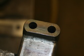
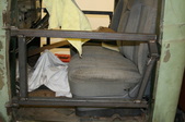
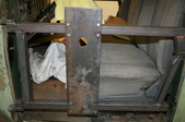
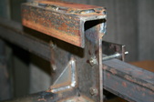
 My plan was to use the door hinges and latch as the mounting points for lifting and spinning as it's fairly central. On the door latch side I ground some thick metal down to where it was smaller than the factory double hook assembly. I welded it to the box tubing I'm using for the framework after drilling the holes. My plan was to use the door hinges and latch as the mounting points for lifting and spinning as it's fairly central. On the door latch side I ground some thick metal down to where it was smaller than the factory double hook assembly. I welded it to the box tubing I'm using for the framework after drilling the holes.
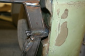
|  Top bar is connected in 2 spots and the lower is hanging on just the hinge. Now I need to bring them together to be a solid, one piece unit. Spacer are used on purpose on the hinge side in case their are cab variances in future projects. Top bar is connected in 2 spots and the lower is hanging on just the hinge. Now I need to bring them together to be a solid, one piece unit. Spacer are used on purpose on the hinge side in case their are cab variances in future projects.
|  Relieved and weld as one unit. A chop saw makes this stuff quick. Relieved and weld as one unit. A chop saw makes this stuff quick.
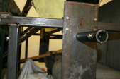
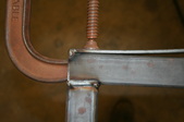
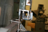
| 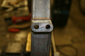 End view shows where socket head cap screws will attach to latch mount. I can use a thin strip of poly when final painted to avoid scratches. End view shows where socket head cap screws will attach to latch mount. I can use a thin strip of poly when final painted to avoid scratches.
|
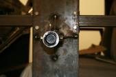
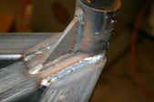
 Finish welding all the sides. Fits nice plenty strong. Finish welding all the sides. Fits nice plenty strong.
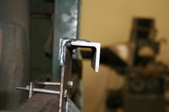
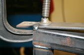
|  Close up shows how you have to angle it to get into the recess. I wanted t screws to be as short as possible. Close up shows how you have to angle it to get into the recess. I wanted t screws to be as short as possible.
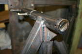
| 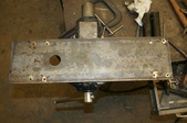 I'm using a plate with double wall pipe for the 1" rod to pass through. The rod will be the spinning axis. I want some adjustment as I don't know the weights centerline so the plate with have to be "slideable" I'm using a plate with double wall pipe for the 1" rod to pass through. The rod will be the spinning axis. I want some adjustment as I don't know the weights centerline so the plate with have to be "slideable"
|  Simple bolts with a plate on the back will do the trick. Simple bolts with a plate on the back will do the trick.
|
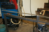
 You can see what I'm going for here. You can see what I'm going for here.
|  Mounted both side up and put in the double wall pipe. I'll slide the rod in and tack up so the holes will be aligned correctly. Mounted both side up and put in the double wall pipe. I'll slide the rod in and tack up so the holes will be aligned correctly.
|  I cut out some angle gussets for added strength. Overbuilt I know, but I don't like doing things twice. I cut out some angle gussets for added strength. Overbuilt I know, but I don't like doing things twice.
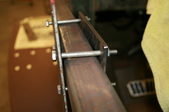
|  On the top of the door plate I welded 2 runs of angle iron. One acts as a guide or locking system and the other is for added strength. The overhead bar will slide into this for lifting. It'll all make more sense with future pics. On the top of the door plate I welded 2 runs of angle iron. One acts as a guide or locking system and the other is for added strength. The overhead bar will slide into this for lifting. It'll all make more sense with future pics.
|
 Better view of it. Better view of it.
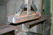
|  This is the overhead lifting bar. Needs to be strong so I'm adding a stretcher/bridger. For the lower bar to bend the strap steel has to "stretch", this is how you increase the lifting capability a lot. I first weld a spacer block in the center. This is the overhead lifting bar. Needs to be strong so I'm adding a stretcher/bridger. For the lower bar to bend the strap steel has to "stretch", this is how you increase the lifting capability a lot. I first weld a spacer block in the center.
|  Then I bend the ends down and tack weld it with a C clamp holding it. Then I bend the ends down and tack weld it with a C clamp holding it.
|  Move the C clamp in more and weld a couple of beads which tightens it all up. If it bows it the other way, all the better. Move the C clamp in more and weld a couple of beads which tightens it all up. If it bows it the other way, all the better.
|
 Welded down arms with gussets and repeated angle slides on the bottom. It all slip together quickly and you safety lock it with either bolts or Vise Grips. Welded down arms with gussets and repeated angle slides on the bottom. It all slip together quickly and you safety lock it with either bolts or Vise Grips.
|  More angle gussets for strength. More angle gussets for strength.
| 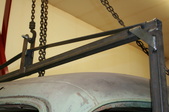 Top view and it's coming together. Top view and it's coming together.
|  Ready to lift off. I made the overhead frame as well from I beam and box tubing. You can see some of the same strengthening methods used on it too. Ready to lift off. I made the overhead frame as well from I beam and box tubing. You can see some of the same strengthening methods used on it too.
|
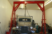
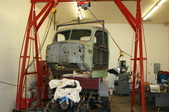 Cab off and I actually rolled the frame forward with the bed on. Loads better than the plank I used to put it on. Cab off and I actually rolled the frame forward with the bed on. Loads better than the plank I used to put it on.
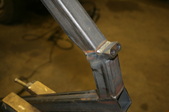
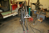
|  Next was the wheels for the spinner. I decided on an A frame designs and weld a double wall tube at the top. Using box tubing on this as well. Next was the wheels for the spinner. I decided on an A frame designs and weld a double wall tube at the top. Using box tubing on this as well.
|  Tubing cut on angle and gusset again for stability. Tubing cut on angle and gusset again for stability.
|  Wheels are unidirectional and larger for easy rolling. I weld nuts onto the double wall tubing and use bolts to lock it down in the position I want to be working on. Bolts on the end keep it all together. Wheels are unidirectional and larger for easy rolling. I weld nuts onto the double wall tubing and use bolts to lock it down in the position I want to be working on. Bolts on the end keep it all together.
|
 You can see all the bolts here and I'll add more later. You can see all the bolts here and I'll add more later.
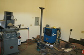
| 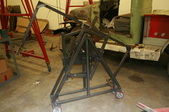 This is the complete unit, minus 1 inch bar. It's easy moved and pretty compact. This is the complete unit, minus 1 inch bar. It's easy moved and pretty compact.
|  narrow enough to store along a wall. narrow enough to store along a wall.
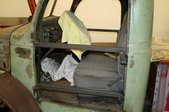
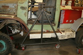
| 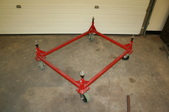 This is the cab mover I made to haul and store cabs. The posts can be change, heightwise as they are just 1 inch rod. That way when painting a cabs outside you can jack it up off the floor to your desired level. This is the cab mover I made to haul and store cabs. The posts can be change, heightwise as they are just 1 inch rod. That way when painting a cabs outside you can jack it up off the floor to your desired level.
|
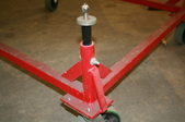 I use this to haul cabs as well. I take off the wheels and run chains through the gussets. Texas to Ohio went great recently. I use this to haul cabs as well. I take off the wheels and run chains through the gussets. Texas to Ohio went great recently.
| 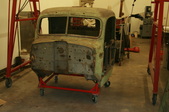 With cab on mover it's very easy to move around. With cab on mover it's very easy to move around.
| 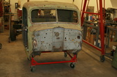 This way there is no chance of the skirts below the doors getting messed up. This way there is no chance of the skirts below the doors getting messed up.
| |
