 | 1.
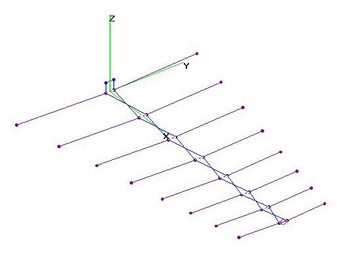
EU 15-El FLAT LPDA - OPT (15Feb2019)EURO UHF 15-Element FLAT LPDA (Log Periodic Dipole Array) analyzed using 4nec2 after Optimization
using nikiml's Python Scripts. For 470-862 MHz EURO UHF Band.
In an LPDA, the Rear Element Length is about a half-wavelenght long at the lowest Frequency (e.g. 470 MHz).
Separation between the REAR Element and the NEXT FORWARD is determined by SIGMA = Dij/2*Lj, which
(with TAU) directly determines the overall LPDA Length. "Best" SIGMA is searched for using nikiml's Optimizer.
In the (Classic LPDA) Analysis below, Each subsequent Element Length is shorter than the preceding
by the factor TAU and each subsequent Element Spacing is shorter than the preceding, also by the factor
TAU = Li/Li+1 = Dij/Djk. Flat Boom Width = Element Width is determined using nikiml's Optimizer.
UHF Raw Gain = 9.9 to 10.6 dBi, F/B & F/R Ratio Min. = 25.7 dB and SWR (75-ohms) Under 1.5. |
| 1682 Visits
24 Items
Shared Album | |
|
 | 2.
UHF 4-El-Pair FLAT-Enh1 FFFDLA - OPT (15 Aug 2015)UHF 4-Element-Pair Flat+Enhanced-Element-1 FFDLA (Free-Form Flat Dipole Logarithmic Array)
analyzed using 4nec2 after determining Dimensions using nikiml's Python Optimization Scripts.
Note that this is an ENHANCED version with JUST Front Element Halves extended across
the ENTIRE Width. [Sometimes a mistake leads to a fortuitous discovery.]
BOOM LENGTH = 8.5-in.
UHF Raw Gain = 6.0 to 8.1 dBi, UHF F/B & F/R Ratio Min = 15.6 dB
and SWR (300-ohms) Under 2.0 (Excellent).
Hi-VHF Raw Gain = 2.6 to 1.7 dBi, Hi-VHF F/B & F/R Ratio = 0.1 to 0.3 dB
and SWR (75-ohms) Under 142 is Excessive. |
| 10918 Visits
21 Items
Shared Album | |
|
 | 3.
UHF 7-El-Pair FLAT LPDA - Terk HDTVi/a (11 Aug 2015)UHF 7-Element-Pair Flat LPDA (Log Periodic Dipole Array) with Swept Forward Elements,
aka Terk HDTVi and HDTVa, analyzed using 4nec2.
Note that Characteristic Impedance is 75-ohms and it is POSSIBLE that Amplified model
has an Impedance Matching Network for improved SWR.
BOOM LENGTH =13.5-in.
UHF Raw Gain = 6.0 to 6.9 dBi, F/B & F/R Ratios = 8.4 to 17.0 dB and
SWR (300-ohms) Under 3.9 is Higher than Desired.
Hi-VHF Raw Gain = 3.0 to 2.7 dBi, F/B & F/R Ratios = 0.3 to 0.6 dB and
SWR (300-ohms) Under 110 is Excessive.
EDIT (3Apr2017): Added Elevation Pattern Charts. |
| 2605 Visits
26 Items
Gallery Album | |
|
 | 4.
UHF 7-EL-Pair FLAT LPDA - Silver Sensor (11 Aug 2015)UHF 7-Element-Pair Flat LPDA (Log Periodic Dipole Array) with Swept Back Elements,
aka SILVER SENSOR, analyzed using 4nec2.
Note that Characteristic Impedance is 75-ohms and it is POSSIBLE that Amplified model
has an Impedance Matching Network for improved SWR.
BOOM LENGTH = 11.75-in.
UHF Raw Gain = 6.5 to 7.4 to 7.0 dBi, F/B & F/R Ratio Min. = 16.8 dB and
SWR (300-ohms) Under 2.6.
Hi-VHF Raw Gain = 1.0 to 1.7 to 1.9 dBi, F/B & F/R Ratios = 0.1 to 0.4 dB and
SWR (75-ohms) = 2840 to 400 is Excessive. |
| 1837 Visits
21 Items
Gallery Album | |
|
 | 5.
UHF 7-El LPDA w Shorting Stub - LPCAD34 (8 Dec 2011)UHF 7-Element LPDA calculated by LPCAD34 with Shorting Stub for improved SWR and Gain curves.
TAU=0.9, SIGMA = 0.17, Input Z = 75 ohms, and other entries (incl. all element radius=AWG14) by holl_ands.
Max Width = 12.8-in, Boom Length = 20.4-inches plus 5-inch Shorting Stub (that can be folded FORWARD).
UHF Raw Gain = 9.0 to 7.5 dBi, Poor F/B & F/R Ratio and SWR Under 2.0 [Excellent].
Characteristic Impedance = 75-ohms. LPCAD34 could not calculate a solution for 300-ohms.
Although Gain and SWR are good, F/B & F/R Ratios need improvement.
Alternative design dimensions should be investigated. |
| 3453 Visits
13 Items
Shared Album | |
|
 | 6.
UHF 7-El Wedge vs Layered LPDA - OPT (27 Apr 2015)UHF 7-Element Layered LPDA (Log Periodic Dipole Array with Top and Bottom Arrays parallel to each other)
was found after trying to Optimize the Wedge version (with Inclusive Angle = 2* HalfAngle) and finding that
it was essentially a Layered version...which was then partially Re-Optimized to find the "best" Separation
between the Top and Bottom set of LPDA Elements. Python Optimization Scripts from nikiml were used
to find the "best" set of dimensions.
Some Parametric Charts for increasing Values of Sigma are found at the bottom. Max Raw Gain reaches 9.0 dBi.
SWR (75-ohms) was acceptable for all Wire Sizes, except for larger Sigma's using AWG10 (Relem = 0.051-in).
Optimum Boom-Length is a linear function of Sigma (ONLY) with NO difference for various Wire Sizes.
Boom-to-Boom Separation increased for low values of Sigma, trying to maintain acceptable SWR, until it
becomes excessive for Sigma = 0.02.
Detailed Dimensions for ALL OPTIMIZED LPDA's are included in the below LPDA SPREAD SHEET.
These models did NOT include an (Optional) Shorting Stub, and Optimizer ensured that NONE were NEEDED.
More info re Sigma-Tau LPDA Models can be found here:
http://www.salsburg.com/Log-Periodic.pdf
Additional Design Information is found on fol. webpage for LPCAD...but Sigmas larger than 0.12 were NOT calculated:
http://wb0dgf.com/LPCAD.htm
=================================================
Two versions are analyzed here: a) 7-El Wedge LPDA and b) 7-El Layered LPDA, with ALL SAME Dimensions,
except for Separation between Top & Bottom sets of LPDA Elements.
a) 7-El Wedge LPDA:
Dimensions: BoomLength=18.6-in (along the Hypotenuse), Width=12.56-in, Height=0.5-in at Feedpoint
rising to 0.71-in at the Rear (very small "Wedge" Angle).
UHF Raw Gain = 7.9 to 9.0 to 8.1 dBi, F/B & F/R Ratio Min = 22.5 dB and SWR (75-ohms) Under 1.8.
===============================================================
b) 7-El Twin-Boom (Layered) LPDA:
Dimensions: BoomLength=18.6-in, Width=12.56-in, Height=0.69-in (same all along the Boom).
UHF Raw Gain = 7.9 to 9.0 to 7.9 dBi, F/B & F/R Ratio Min = 21.0 dB and SWR (75-ohms) Under 1.9.
[NOTE: More accurate EVAL found only 0.1 dBi less Gain at 698 MHz, see EVAL RESULTS Files.]
. |
| 2575 Visits
39 Items
Gallery Album | |
|
 | 7.
UHF 7-El FLAT LPDA vs FFFDLA - OPT (14 Jun 2015)UHF 7-Element FLAT LPDA (Log Periodic Dipole Array) vs FFFDLA (Free Form Flat Dipole Logarithmic Array)
analyzed using 4nec2 after Optimization using nikiml's Python Scripts.
In an LPDA, the Rear Element Length is about a half-wavelength long at the lowest Frequency (e.g. 470 MHz).
Separation between the REAR Element and the NEXT FORWARD is determined by SIGMA = Dij/2*Lj, which
(with TAU) directly determines the overall LPDA Length. The "Best" SIGMA is searched for using nikiml's Optimizer.
In the first (Classic LPDA) Analysis below, each subsequent Element Length is shorter than the preceding
by the factor TAU and each subsequent Element Spacing is shorter than the preceding, also by the factor
TAU = Li/Li+1 = Dij/Djk. Flat Boom Width = Element Width is determined using nikiml's Optimizer.
In the second FFFDLA Analysis, the Spacings between Elements is still reduced by the factor TAU, but the
Elements Lengths as well as Element & Boom Widths are FREE FORM, INDEPENDENT Variables, which resulted
in some "interesting" (and repeatable) dimensions with just marginally better performance.
======================================
a) Element Width = Boom Width = 1.5 in:
UHF Raw Gain = 7.5 to 8.7 to 8.4 dBi, F/B & F/R Ratio Min = 17.8 dB and SWR (75-ohms) Under 1.6.
======================================
b) Free-Form Dipole Logarithmic Array (FFDLA), Independently Variable Element Widths, Lengths & Boom Width
with Log Sigma Separations:
UHF Raw Gain = 7.7 to 8.6 dBi, F/B & F/R Ratio Min = 24.5 dB and SWR (75-ohms) Under 1.5. |
| 1835 Visits
30 Items
Shared Album | |
|
 | 8.
UHF 7-El VEE LPDA + Shorting Stub - Opt (13 Jun 2013)UHF 7-Element "VEE" LPDA (Log Periodic Dipole Array) with Shorting Stub and Variable Sweep Angle,
Optimized using nikiml's Python Scripts, then analyzed using 4nec2. Note that Shorting Stub
orientation can be above, behind, below or even ALONG the boom. See 4nec2 File for dimensions.
Raw Gain of 8 dBi (+/- 0.2 dB) was VERY FLAT, slightly more than irregular Raw Gain in VA3RR's 8-El LPDA.
F/B & F/R Ratios were also improved compared to VA3RR's. Both had excellent SWR.
Note that this design ASSUMES the use of a "Shorting Stub" at the back of the Antenna (0.609-inch long).
If this is omitted, there will be a severe mid-band Raw Gain HOLE and a mid-band SPIKE in the SWR.
A design without the Shorting Stub would require a different optimization.
"VEE" LPDA myth would lead us to believe that a forward sweep in the range of 30-45 degrees
would provide the best performance. HOWEVER, in the several runs I've conducted for
7-El LPDAs with and without Shorting Stubs and various optimization parameters,
the "best" angle was found to be in the range of +/- 4 degrees....very close to a non-swept LPDA.
I was surprised to see a Sweep Angle of MINUS 3.9 in the Optimized LPDA...slightly towards the REAR.
I also conducted optimization runs with Angle fixed at 15, 30, 40 & 45 degrees...none were better.
L.B. Cebik discussed this myth in the fol. white paper: http://w4rnl.net46.net/download/v1.pdf
Equations, Charts and other info re LPDA found here: http://www.salsburg.com/Log-Periodic.pdf
In search of the optimum Forward Sweep Angle in a "VEE" LPDA, I constructed a 4nec2 file with
SIX VARIABLES that could be Randomly searched using nikiml's Python Optimization Scripts
to find the "best" combination of Forward Sweep Angle (from Y-Axis), Tau =Li/Li+1 = Dij/Djk,
Sigma = Dij/2*Lj, Feedline Impedance, Length of Longest Element (determined by Lowest Design Freq)
and Length of the Shorting Stub (which I found improved SWR and esp. Gain smoothness).
It was NOT necessary to stipulate either the Boom Length or the Highest Design Freq,
the above parameters providing a complete description of the LPDA, relying on Python
Optimization to do a "best fit" against desired Frequency Response stipulated in *.bat file.
BTW: Initially I tried an optimization matched to 300-ohms, but the SWR was somewhat higher
than desired (3.3:1), with a slightly better match to 75-ohms, with the resultant design best
matched to 150-ohms. So 300-ohm LPDA is possible, but trying to match impedance degrades
trying to maximize Gain, F/R & F/B Ratios. So LPDA's are best when matched to 75-ohms.
I also tried optimizations which didn't try to also search for best F/B & F/R Ratios.
Raw Gain was nearly 1 dB higher, but F/B & F/R Ratios had dips to only about 6 dB, so it's
not reported here (just like LPCAD34's 7-El LPDA analyzed is a separate album).
EDIT (13Jun2013): Filename was mislabeled...results are for 7-Element LPDA and NOT 8-Element,
making the performance improvement even more impressive..... |
| 3135 Visits
19 Items
Shared Album | |
|
 | 9.
UHF 8-El VEE LPDA + Shorting Stub - Opt (12 Jun 2013)UHF 8-Element "VEE" LPDA (Log Periodic Dipole Array) with Shorting Stub and Variable Sweep Angle,
Optimized using nikiml's Python Scripts, then analyzed using 4nec2. Note that Shorting Stub
orientation can be above, behind, below or even ALONG the boom.
See 4nec2 File for Dimensions: about 16-in Wide x 12-in Wide.
Raw Gain of 8.6 dBi (+/- 0.2 dB) was VERY FLAT, about 1 dB more than irregular Raw Gain
in VA3RR's 8-El LPDA (used in oldsparks build and GHZ24 Parabolic designs).
F/B & F/R Ratio Minimum = 27.2 dB and SWR (75-ohms) under 1.4 were also improved compared
to VA3RR's, although both had excellent SWR.
Note that this design ASSUMES the use of a "Shorting Stub" at the back of the Antenna (0.68-inch long).
If this is omitted, there will be a severe problems in Raw Gain and SWR.
A design without the Shorting Stub would require a different optimization.
"VEE" LPDA myth would lead us to believe that a forward sweep in the range of 30-45 degrees
would provide the best performance. HOWEVER, in the several runs I've conducted for
7-El & 8-El LPDAs with and without Shorting Stubs and various optimization parameters,
the "best" angle was found to be in the range of +/- 4 degrees....very close to a non-swept LPDA.
I was surprised to see a Sweep Angle of MINUS 2.7 in the Optimized LPDA...slightly towards the REAR.
L.B. Cebik discussed this myth in the fol. white paper: http://w4rnl.net46.net/download/v1.pdf
Equations, Charts and other info re LPDA found here: http://www.salsburg.com/Log-Periodic.pdf
In search of the optimum Forward Sweep Angle in a "VEE" LPDA, I constructed a 4nec2 file with
SIX VARIABLES that could be Randomly searched using nikiml's Python Optimization Scripts
to find the "best" combination of Forward Sweep Angle (from Y-Axis), Tau =Li/Li+1 = Dij/Djk,
Sigma = Dij/2*Lj, Feedline Impedance, Length of Longest Element (determined by Lowest Design Freq)
and Length of the Shorting Stub (which I found improved SWR and esp. Gain smoothness).
It was NOT necessary to stipulate either the Boom Length or the Highest Design Freq,
the above parameters providing a complete description of the LPDA, relying on Python
Optimization to do a "best fit" against desired Frequency Response stipulated in *.bat file. |
| 2749 Visits
15 Items
Shared Album | |
|
 | 10.
UHF 8-El LPDA - VA3RR (25 May 2013)UHF 8-Element LPDA (Log Periodic Dipole Array) by VA3RR (and GHZ24) analyzed using 4nec2 for
three different models, based on three different physical implementations:
a) 4nec2 File from VA3RR's webpage, which uses SIMULATED Zig-Zag Transmission Line (TL).
I re-segmented and formatted to my usual 4nec2 format: http://www.qsl.net/va3rr/hdtv/HDTV.htm
This version has also been used by GHZ24 as a Parabolic Reflector antenna Feed.
Beamwidth is very wide 60-70 degrees. Note small glitch near 698 MHz for Raw Gain, F/B and F/R Ratios.
Although probably not large enough to cause problems, this can be cured by adding a shorting stub:
UHF Raw Gain = 7.2 - 7.7 dBi, F/B & F/R Ratio Min = 14 dB (most above 20 dB) and SWR Under 1.3.
======================================
b) An LPDA was fabricated by user "oldsparks" using 7/32-in Twin-Boom and AWG10 Elements
rather than Zig-Zag Transmission Line (which would be more difficult to construct).
It loses about 0.5 dB in the process:
UHF Raw Gain = 6.8 - 7.3 dBi, F/B & F/R Ratio Min = 14 dB and SWR Under 1.2.
======================================
c) Since 7/32-in Twin-Boom is a bit of an overkill, a similar LPDA was analyzed using
AWG10 for the Twin-Boom as well as the Elements, plus a Shorting Stub. Dimensions
were determined using nikiml's Python Optimization Scripts, providing flatter Gain,
higher F/B & F/B Ratios and low SWR:
UHF Raw Gain = 7.3 - 7.8 dBi, F/B & F/R Min = 22.4 dB and SWR Under 1.4. |
| 3597 Visits
45 Items
Shared Album | |
|
 | 11.
UHF 9-El LPDA w Shorting Stub - LPCAD34 (20 Dec 2011)UHF 9-Element Log Periodic Dipole Array (LPDA) with (and without) Shorting Stub analyzed using 4nec2.
Without the Shorting Stub, performance was significantly degraded.
UHF Raw Gain = 9.0 to 9.2 to 8.6 to 8.8 to 8.0 dBi, F/B & F/R Ratios Under 20 dB and SWR (75-ohms) Under 1.8.
Dimensions calculated by LPCAD34, entering Boom Length (18-in), Number of Elements (9), Rear Element Diameter (AWG10)
and High/Low Frequency Rolloffs (470/698) (see 4nec2 File). [Other dimensions will generate different results.]
Characteristic Impedance = 75-ohms. LPCAD34 could not calculate a solution for 300-ohms.
LPCAD34 generated a 4nec2 file, but the Shorting Stub was missing the Shorting Wire (GW10), resulting in a
strange attachment off to the side of the front element.
I added a definition of GW10 to the 4nec2 file, with the stub pointed directly upwards from the rear element
to facilitate varying the length and provide better visibility.
Since LPCAD34 did NOT calculate the requisite Shorting Stub Length, I defined "SLL" as a SYmbol variable
and performed an optimization using nikiml's python scripts. Over range of 0.1-5-in, 1.04-in was optimum.
Looking at the charts, it was determined that a more optimized performance was possible if the size
were SMALLER by F=0.97, which reduced SWR and improved F/B & F/R Rations on the highest freqs.
Apply this correction to all dimensions in the 4nec2 file. It is already applied to below diagrams.
Below LPDA_uhf.doc contains *.bat file for running the scripts, where it was necessary to DISABLE Autosegmentation (OFF=0),
since nikiml's scripts did not properly keep the Transmission Lines (TL Cards) on the middle segments when autosegmenting.
Note that the target-function is a joint optimization of Mismatch-Loss, Gain and Front-To-Rear Ratio.
To increase Gain on higher frequencies, a new design with a 10 to 30-percent larger high frequency rolloff
parameter (FH) should be investigated. |
| 4100 Visits
14 Items
Shared Album | |
|
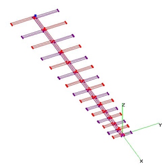
 | 12.
UHF 13-El Twin-Boom LPDA - OPT (13 May 2015)UHF 13-Element Twin-Boom (Layered) LPDA (Log Periodic Dipole Array) with Dimensions Optimized
for Highest Gain (i.e. Sigma = 0.18) using nikiml's Python Scripts.
Boom-Length = 36.7-inches. Detailed Dimensions found in below Word *.doc file (formatting errors in *.pdf).
UHF Raw Gain = 10.6 to 11.0 to 10.2 to 10.6 dBi, F/B & F/R Ratio Min = 25.0 dB and SWR (75-ohms) under 1.6.
Note that Max UHF Raw Gain occurs when Sigma = 0.213 (per Optimization) and 0.22 (per Parameter Study),
but Quasi-Optimum Sigma = 0.18 is nearly SAME Performance, with much shorter Length, as analyzed here.
This Webpage includes Spread Sheets and Results Images for a Larger Number of Different LPDA's,
illustrating how the Optimized, Max Gain increases as the number of Element Pairs is increased.
Boom Length (and Gain) also increases as OPTIMIZED SIGMA increases [SIGMA is Normalized Spacing between Elements].
Note that there IS INDEED an OPTIMUM BOOM LENGTH for each choice of the number of Element Pairs,
so there is NO ADVANTAGE to simply making the Boom any Longer
and making the Boom SHORTER for a given number of Element Pairs REDUCES the Gain from Optimum.
So you can say that a Longer Boom has more Gain....but it requires ADDING the RIGHT Number of Element Pairs.
And since SIGMA also increases, the DENSITY of Element Pairs per Foot remains more of less the SAME. |
| 1932 Visits
23 Items
Gallery Album | |
|
 | 13.
UHF 14-El (300-ohms) LPDA - dnes (8 Dec 2011)UHF 14-Element Log Periodic Dipole Array (LPDA) Antenna analyzed using 4nec2. NOTE: 300-ohm characteristic impedance.
4nec2 file with variable SYmbols from Walter Dnes on 9Sep2010 (33-in Boom Length), with a few mods by holl_ands to improve high freq performance:
http://www.digitalhome.ca/forum/showthread.php?p=1151493
This thread contains lots of useful LPDA information. |
| 3388 Visits
13 Items
Shared Album | |
|
 | 14.
UHF 14-El VEE LPDA + Shorting Stub - OPT (14 Jul 2013)UHF 14-Element "VEE" Log Periodic Dipole Array (LPDA) Antenna with Shorting Stub,
Optimized using nikiml's Python Scripts, then analyzed using 4nec2.
Optimum sweep angle was about 2 degrees to the REAR, similar to other Optimized "VEE" LPDAs,
which is very close to a non-swept LPDA.
Raw Gain increased ONLY about 1 dB more than 8-El "VEE" LPDA, illustrating the biggest
disadvantage of LPDA vs Yagi Antennas. However, F/R & F/R Ratios were HUGE with
very good SWR (but for 75-ohms so must use a 1:1 Balun).
UHF Raw Gain = 11.8 to 10.4 dBi, F/B & F/R Ratio Min. = 22.2 dB and SWR (75-ohms) Under 1.4.
NOTE: Python Control *.bat text File presumes that all test files are in the c:\Python33 sub-directory,
whereas all earlier postings have presumed c:\Python27, so adjust as necessary.
My num-cores=6 (aka "threads" for i5 & i7 with 2 threads per core) also needs to be set
for your processor. I just upgraded desktop from AMD Phenom II X3 to X6 (used here) and on
i7 Laptop I reserve one "thread" for web surfing & checking prelim results, so num-cores=7. |
| 2346 Visits
16 Items
Shared Album | |
|
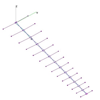
 | 15.
UHF 15-El FLAT LPDA - OPT (14 Jun 2015)UHF 15-Element FLAT LPDA (Log Periodic Dipole Array) analyzed using 4nec2 after Optimization using nikiml's Python Scripts.
In an LPDA, the Rear Element Length is about a half-wavelenght long at the lowest Frequency (e.g. 470 MHz).
Separation between the REAR Element and the NEXT FORWARD is determined by SIGMA = Dij/2*Lj, which
(with TAU) directly determines the overall LPDA Length. "Best" SIGMA is searched for using nikiml's Optimizer.
In the first (Classic LPDA) Analysis below, Each subsequent Element Length is shorter than the preceding
by the factor TAU and each subsequent Element Spacing is shorter than the preceding, also by the factor
TAU = Li/Li+1 = Dij/Djk. Flat Boom Width = Element Width is determined using nikiml's Optimizer.
In the second Analysis, the Boom Width ALSO was shorter by the same factor TAU, with the REAR Boom Width
determined by the Optimizer, resulting in marginally better performance on some Frequencies.
=====================================
a) Element Width = Boom Width = 0.75 in:
UHF Raw Gain =10.7 to 11.0 to 10.4 to 11.0 to 10.6 dBi, F/B & F/R Ratio Minimum = 26.9 dB and SWR (75-ohms) Under 1.7.
=====================================
b) Tapered Element & Boom Widths:
UHF Raw Gain = 11.1 to 10.7 to 11.4 to 10.4 to 11.0 dBi, F/B & F/R Ratio Min = 27.2 dB and SWR (75-ohms) Under 1.5. |
| 2282 Visits
30 Items
Gallery Album | |
|
 | 16.
UHF 45-El LPDA - ZS6BTE (24 Dec 2008)UHF Band (Ch2-69), 45-Element (!!!), 126-inch LPDA (Log Periodic Dipole Array), using zig-zag feedline.
From ZS6BTE article "Wideband Antennas for the TV DXer", no longer on QST.NET. |
| 2764 Visits
7 Items
Shared Album | |
| |
