 | 1.
UHF H4 2x2-Bay Bowtie - NO Refl (2 Mar 2013)UHF Horizontal 4-Bay (H4), 2x2-Bay Bowtie (NO Reflector) Antennas analyzed using 4nec2. Except for
Bowtie Sweep = 0, ALL of the fol. parameters were allowed to vary in nikiml's Python Optimization scripts.
Note that H4 2x2-Bay had about 0.5 dB higher Raw Gain, narrower Beamwidth & better SWR than M4 4-Bay:
http://imageevent.com/holl_ands/multibay/4bay/super4m10x95 [All AWG10 makes very little difference.]
a) UHF H4, 2x2-Bay Bowtie with RF Combiner Mod analyzed using 4nec2. Does NOT include Insertion
and Amplitude/Phase Mismatch Loss in Baluns and RF Combiner ("typically" 0.5-1.5+ dB).
Note that this presumably "perfect" combiner version provided LESS Gain than the version
using a Horizontal Harness and would lose even more in the RF Combiner device.
UHF Raw Gain = 10.0 to 12.7 dBi and SWR (300-ohms) under 2.8.
Hi-VHF Raw Gain = 3.1 - 3.8 dBi and SWR (300-ohms) = 30 to 9 (Excessive).
BowLen=10.5-in (AWG10 Elements), BowSep=12.5-in, TineSep=9.25-in, BowSwp=0.0-in.
FeedSep=1.0-in (AWG10), Left/Right Bay Separation YBay=20.0" (Center-Center).
Baluns connect to center (Simulated) SOURCE Wires in L & R 2-Bays and then to an RF Combiner.
====================================
b) UHF H4, 2x2-Bay Bowtie with Horizontal Harness instead of Two Transmission Lines.
Height=20.5-inches, Width=51.2-inches.
UHF Raw Gain = 11.1 to 12.8 dBi and SWR (300-ohms) under 2.3.
Hi-VHF Raw Gain Max = 4.1 to 5.0 dBi and SWR (300-ohms) = 7.3 to 5.0 (Excessive).
BowLen=11.25-in (AWG10 Elements), BowSep=12.5-in, TineSep=8.0-in, BowSwp=0.0-in.
FeedSep=3.25-in (AWG10), Left/Right Bay Separation YBay=27" (Center-Center).
Horizontal Harness Separation between two FEEDLINE wires: FeedSep=3.25-in,
From Y=0 to Centerline for each of the two 4-Bays: YBay=27-in. |
| 7341 Visits
39 Items
Shared Album | |
|
 | 2.
UHF 2x2-Bay Narrow - NO Refl (2 Mar 2013)UHF 2x2-Bay Bowtie (NO Reflector), NARROWER WIDTH with Bay-Bay Separation = 10-in
and 2-in Vertical Spurs on Whiskers, analyzed using 4nec2. This smaller version is as much as 3.5 dB
lower Raw Gain than an Optimized full-size version without Vertical Spurs.
Since an in-window mount was the target application, AWG10 wire size was assumed.
a) UHF 2x2-Bay Bowtie (Narrower) with Two Transmission Lines from a common SOURCE Wire was Optimized
(using nikiml's Python Scripts). Bowtie-Bowtie Separation was FIXED at 9.0-inches, with all FIVE
other parameters as VARIABLES. Maximum constraints were imposed on Whisker Length and
Feedline Separation to also limit overall antenna width. Width=38.5-in, Height=14.0-in.
BowLen=8.5-in (AWG10 Elements), VertSpurs=2.0-in, BowSep=9.0-in, TineSep=5.0-in, BowSwp=0.0-in.
FeedSep=2.0-in (AWG10), Left/Right Bay Separation YBay=20.0" (Center-Center).
Two Transmission Lines: Impedance=450-ohms, Length=11 (to 12) inches (Balun to Feedlines).
b) UHF 2x2-Bay Bowtie (Narrower) with Horizontal Harness from a common SOURCE Wire was Optimized
(using nikiml's Python Scripts). Bowtie-Bowtie Separation, Whisker Length & Tine Separation
was as determined in para a) above. Harness Separation between the two Transmission Lines
(determines Impedance), distance BEHIND Bowties and Bowtie Feedline Separation were all VARIABLES.
Width=38.25-in, Height=14.0-in.
BowLen=8.5-in (AWG10 Elements), VertSpurs=2.0-in, BowSep=9.0-in, TineSep=5.0-in, BowSwp=0.0-in.
FeedSep=2.0-in (AWG10), Left/Right Bay Separation YBay=20.0" (Center-Center).
Horizontal Harness Separation = 2.125-in, Separation behind Bowties = 3.825-in.
Substituting thinner AWG12 (without re-optimizing dimensions) will slightly increase SWR
(from under 2.0 to under 2.6), with no change to Raw Gain.
Raw Gain is about 2.5 dBi higher on the broad maximum across the higher frequencies than it is on 470 MHz.
This is frequently desired to overcome higher Balun, Coax and (if no Preamp) RF Splitter Loss on the higher
frequencies. Note that Horizontal Harness acts as a REFLECTOR....which
is why it is important to make sure that it is on the BACKSIDE of the (NO Reflector) Antenna.
With a Reflector, it MAY turn out it needs to be on the FRONT (like CM4228/CM4228HD).
Minimizing SWR wasn't easy....changing SOME dimensions by more than about 1/4-inch can change SWR.
Hi-VHF Raw Gain with the Horizontal Harness (Reflector) adds about 0.5 dB Gain more than the 2xTL version,
with about 3.5 dBi. However, the SWR is excessive, which may or may not degrade performance on weak stations. |
| 2509 Visits
33 Items
Shared Album | |
|
 | 3.
UHF H4 2x2-Bay Bowtie - 10 Refl Rods (21 Mar 2013)UHF Horizontal 4-Bay (H4), aka 2x2-Bay Bowtie with 10 Reflector Rods analyzed using 4nec2 after
determining "Best" Dimensions using nikiml's Python Optimization Scripts.
Optimized Dimensions were determined by running a series of nikiml's Python Optimization Scripts,
adjusting the Target Levels and esp. Target Function "weights" as necessary to find the desired
balance of Raw Gain, F/B & F/R Ratio and SWR (Mismatch Loss).
In preliminary Optimization searches, it became apparent that the lowest SWR performance was
being found when there was either two Reflector Rods centered behind each Harness Wire.
Or a Reflector Rod directly behind each Harness wire....as was designed into the below model.
Locating the Horizontal Harness BETWEEN the Bowties and the Reflector Rods provided 1.4 dB
MORE Raw Gain acting as a DIRECTOR than when placed in FRONT of the Bowties (since inferior,
will not be shown).
UHF Raw Gain = 12.2 to 14.8 dBi
UHF F/B & F/R Ratio Min = 20 dB
UHF SWR (300-ohms) Max = 2.4
UHF Beamwidth = 30 to 20-degrees, about half as much as an M4 4-Bay.
Hi-VHF Raw Gain Typ. 6.5-7.3 dBi
Hi-VHF F/B & F/R Ratio Typ. 7-10 dB
Hi-VHF SWR (300-ohms) is Excessive [Which may or may not be a problem in any given situation....]
Horizontal Harness interconnecting the pair of 2-Bay Bowties was specifically designed for
EQUAL Length in each wire by setting end points precisely in the Center of each Bay and
then connecting from there diagonally to Feedline wires. Overall Harness Wire Length is
changed in Optimization Scripts by moving Harness closer or further away from plane of the
Bowties and the Impedance is adjusted by the separation between the two Harness Wires.
The Optimization Script does a random search of ALL applicable variables to find the "Best" set
of Dimensions which will maximize Raw Gain, F/R and F/B Ratios with an "acceptable" SWR level.
In preliminary runs, slightly higher Raw Gain was found as separation between Left and
Right 2-Bays was increased. However, forward sidelobe levels also increase to what I believe
are unacceptably higher levels.
Hence final Optimization search was limited to Center-Center 2-Bay Separation between
20-24 inches, with "best" result at my imposed maximum: 24-inches. Even better forward
sidelobe suppression is found when Optimizing with 20-in constraint (not shown). |
| 6800 Visits
18 Items
Shared Album | |
|
 | 4.
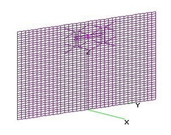
UHF 2x2-Bay (H4) with Building Reflector (21 Jul 2014)UHF 2x2-Bay Bowtie (H4) with Building used as a Reflector analyzed using 4nec2.
Separation from side of Building was assumed to be 4.5-inches.
UHF Raw Gain = 14.5 to 16.1 to 15.4 dBi, Raw Gain Min = 20.8 dB and SWR (300-ohms) under 2.9.
HUGE Reflector improved Raw Gain by about 2 dB across UHF Band, compared to 10 Reflector Rod version.
To improve low frequency SWR with minor Gain loss, increase to 5.0-inches.
I also did a run with H4 centered on the Building, which improved max SWR=2.6, with
a nearly identical Raw Gain curve. |
| 1876 Visits
15 Items
Gallery Album | |
| |
