 | 1.
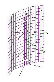
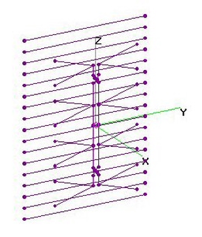
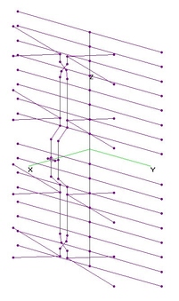
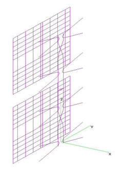
Ch22 FF4 4-Bay Bowtie + DAR (15Jan2019)Ch22 FF4 4-Bay Bowtie with Variable Double Angle Reflector (VDAR) analyzed using 4nec2.
Two versions are presented. Dimensions are found in the 4nec2 Text Files:
A) Optimized for JUST Forward Gain and SWR:
VDAR is same as TWO Stacked UHF Band FF4 VDARs, hence Twice as tall [96-in H].
Raw Gain = 18.2 dB, F/B & F/R Ratios = 12.3 dB and SWR under 2.0.
B) Optimized for Forward Gain, SWR, F/B & F/R Ratios:
T.B.D. |
| 181 Visits
12 Items
Shared Album | |
|
 | 2.
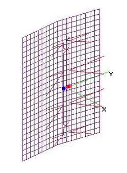
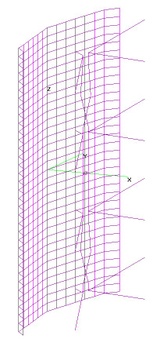
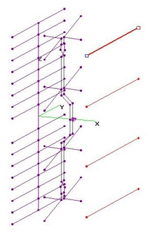
NEW UHF Free-Form 4-Bay + FlatScreenRefl (19 Jul 2017)NEW-UHF [470-608 MHz] Free-Form 4-Bay (NU-FF4) Bowtie Antennas with Flat Screen Grid Reflector
analyzed using 4nec2. Dimensions were Optimized using nikiml's Python Scripts, including
Angle of Reflector's outer "wings"....which was nearly ZERO...essentially FLAT.
Dimensions for VARIABLE DOUBLE ANGLE REFLECTOR are 48 H x 36-in W (unfolded),
with 2x2-in GRID assumed for this model to speed up Optimization Execution Time and stay
within 4nec2 and NEC2 parameter constraints, incl. Total Number of Segments.
If higher F/B and/or F/R Ratios are desired, reduce Grid Vertical Spacing to 1-in or 0.5-in.
UHF Raw Gain = 15.3 to 16.2 dBi, F/B & F/R Ratio Min = 16.6 dB and SWR (300-ohms) under 2.2.
Hi-VHF Raw Gain = 8.8 to 8.9 dBi, F/B & F/R Ratio Min = 12.0 dB and SWR (300-ohms) = 33 to 22 [Excessive].
Compared to Old UHF Band FF4, we see Gain of 0.7 dB on 470 MHz and 1.1 dB on 608 MHz:
UHF Raw Gain = 14.6 (470 MHz) to 15.0 (608 MHz), 16.2 (674 MHz) peaking at 17.1 dBi (698 MHz)
UHF F/B & F/R Ratio Min = 14.8 dB [GOOD] and SWR (300-ohms) under 2.1.
Hi-VHF Raw Gain = 10.8 to 8.3 dBi, F/B & F/R Ratio Min = 10.9 dB [FAIR] and SWR (300-ohms) = 34 to 23 (Excessive).
https://imageevent.com/holl_ands/multibay/4bayrefl/uhffreeform4baydblanglreflopt
DIMENSION STATEMENTS: [May Round to nearest 1/4-inch]
' Radius (in inches) of BOWTIE elements:
SY Rbow=0.051 [AWG10]
' Radius (in inches) of FEEDLINE wires:
SY Rfeed=0.051 [AWG10]
' Separation at Crossover:
SY Hop=1.0
' Conductivity (Copper=3.0e7, Alum=2.0e7, StainlessSteel=1.67e7):
SY Cond=3e+07
' Distance between the centers of the two INNER bowties:
SY ZBowII=14.72
' From center of INNER bowtie to center of OUTER bowtie:
SY ZBowOI=12.10
' INNER Bow Whisker Length (lose some in bend):
SY BowLeni=13.13
' OUTER Bow Whisker Length (lose some in bend):
SY BowLeno=8.53
' INNER Bow Forward Sweep distance at tip of the whisker:
SY BowSwpi=2.51
' OUTER Bow Forward Sweep distance at tip of the whisker:
SY BowSwpo=1.46
' INNER Bow Tine Separation:
SY TineSepi=7.62
' OUTER Bow Tine Separation:
SY TineSepo=3.36
' Separation between two FEEDLINE wires:
SY FeedSep=3.48
' From center of Feedline Cross-Over to center of OUTER Bowtie:
SY ZCross=3.045
' Reflector to Bowtie Separation:
SY RS=3.69
' Bend Sweep (Forward in inches:
SY Bend=0.19 [Essentially Zero]
UPDATE (29Nov2017): Uploaded Images with improved viewability (esp. Thumbnails)
with NO Change to content.
UPDATE (7May2019): Added comparison to Old UHF Band FF4.
UPDATE (17Aug2019): Added Dimension Statements. |
| 8768 Visits
16 Items
Shared Album | |
|
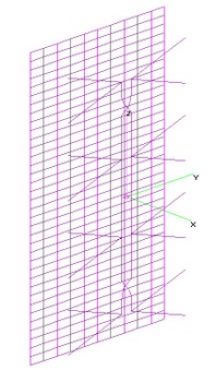
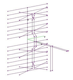
 | 3.
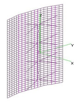
UHF Free-Form 4-Bay + DblAnglRefl (2 Nov 2013)UHF Free-Form 4-Bay (FF4) Bowtie Antennas with various sized Variable Double Angle Reflectors (VDAR)
analyzed using 4nec2. Essentially ALL dimensions were Optimized using nikiml's Python Scripts,
including the Angle of the Reflector's outer "wings".
Pictures of finished FF4's:
http://www.avsforum.com/forum/25-hdtv-technical/2483921-northeast-connecticut-mansfield-trees-trees-trees.html#post44801233
a) FF4 + Reflector = 40"x36" (unfolded), same as mclapp's M4 for backfits & comparison purposes,
but Reflector is Swept Forward 4.375-in vice 2.5-in. Elements and Feedline are AWG10.
When I changed to AWG8 (w/o reoptimizing), FF4 Gain = 14.3 to 15.3 to 14.8 to 15.6 dBi,
with Gain on 470 MHz increasing 0.3 dB, but only 0.1 dB on other freqs.
Compare to M4 (10.0"x9.5") Gain = 13.8 to 15.8 to 15.0 dBi and M4 (9.5"x9.0") Gain = 13.3 to 16.0 dBi.
So FF4 Gain increased as much as 1 dB on 470 MHz, with higher Gain on low to mid-band channels
and about the same on the higher channels, with somewhat lower F/B & F/R Ratios (probably
needs a larger Reflector) and same High Gain in Hi-VHF Band:
UHF FF4 Raw Gain = 15.1 dBi +/- 0.4 dB, dropping to 14.0 dBi on 470 MHz, F/B & F/R Ratio Min = 14.8 dB
[GOOD] and SWR (300-ohms) under 1.8.
Hi-VHF Raw Gain = 8.1 dBi, F/B & F/R Ratio Min = 19 dB [EXCL] and SWR = 16.8 to 15.7 [Excessive].
SUMMARY OF DIMENSIONS FROM 4nec2 FILE (In inches, rounded to nearest 1/8-in):
Rbow=0.051 ' Radius of Bowtie Elements (AWG10, not critical)
Rfeed=0.051 ' Radius of Feedlines (cAWG10, not critical)
Hop=1.0 ' X-Coord Separation of Feedlines at Crossover
ZBowII=12.0 ' From Center of INNER Bowtie to Center of INNER Bowtie, Optimizer found 11.99499
ZBowOI=11.0 ' From Center of INNER Bowtie to Center of OUTER Bowtie, Optimizer found 10.91547
BowLeni=11.5 ' INNER Bow Whisker Length (lose some in bend), Optimizer found 11.59459
BowLeno=12.0 ' OUTER Bow Whisker Length (lose some in bend), Optimizer found 11.95864
BSi=1.5 ' INNER Bow Forward Sweep distance at tip of the Whisker, Optimizer found 1.557153
BSo=5.75 ' OUTER Bow Forward Sweep distance at tip of the Whisker, Optimizer found 5.78872
TineSepi=7.375 ' INNER Bow Tine Separation, Optimizer found 7.344971
TineSepo=6.5 ' OUTER Bow Tine Separation, Optimizer found 6.513835
FS=1.75 ' Separation between two FEEDLINE wires, Optimizer found 1.773704
ZCross=2.625 ' From Center of Feedline Cross-Over to Center of OUTER Bowtie, Optimizer found 2.68731
##################################################################
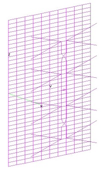
b) FF4 + TALLER Reflector = 48"x36" unfolded), Reflector is Swept Forward 3.375-in vice 2.5-in.
Elements and Feedline are AWG10. Outer Bowties are now much smaller, at SAME Angle as Inner.
Raw Gain increased 0.3 dB on 470 MHz, 1.6 dB more on 698 MHz and eliminated the mid-Band Gain Dip
found in the above AWG10 40x36-in Reflector.
UHF Raw Gain = 14.6 (470 MHz) to 16.2 (674 MHz) peaking at 17.1 dBi (698 MHz),
UHF F/B & F/R Ratio Min = 14.8 dB [GOOD] and SWR (300-ohms) under 2.1.
Hi-VHF Raw Gain = 10.8 to 8.3 dBi, F/B & F/R Ratio Min = 10.9 dB [FAIR] and SWR (300-ohms) = 34 to 23 (Excessive).
SUMMARY OF DIMENSIONS FROM 4nec2 FILE (In inches, rounded to nearest 1/8-in):
Rbow=0.051 ' Radius of Bowtie Wires (AWG10, not critical)
Rfeed=0.051 ' Radius of Feedline Wires (AWG10, not critical)
Hop=1.0 ' Wire Separation at the Feedline Crossover
ZBowII=12.0 ' From Center of INNER bowtie to Center of INNER Bowtie, Optimizer found 11.99729
ZBowOI=10.675 ' From Center of INNER Bowtie to Center of OUTER Bowtie, Optimizer found 10.67465
BowLeni=12.875 ' INNER Bow Whisker Length (lose some in bend), Optimizer found 12.86343
BowLeno=8.125 ' OUTER Bow Whisker Length (lose some in bend), Optimizer found 8.124315
BSi=3.5 ' INNER Bow Forward Sweep distance at tip of the Whisker, Optimizer found 3.496068
BSo=2.25 ' OUTER Bow Forward Sweep distance at tip of the Whisker, Optimizer found 2.273594
TineSepi=6.75 ' INNER Bow Tine Separation, Optimizer found 6.813349
TineSepo=3.875 ' OUTER Bow Tine Separation, Optimizer found 3.875966
FS=2.875 ' Separation between two FEEDLINE wires, Optimizer found 2.82885
ZCross=2.375 ' From Center of Feedline Cross-Over to Center of OUTER Bowtie, Optimizer found 2.406892
##################################################################
c) FF4 with a TALLER and WIDER Reflector alternative is T.B.D.
EDIT (23Mar2016): Added Dimensioned Drawing for Bowtie portion of FF4+VDAR(48x36)
version (b) and replaced associated 4nec2 File with embedded CMD--OPT and CMD--EVAL Commands
(vice original *.bat text File). |
| 12490 Visits
54 Items
Shared Album | |
|
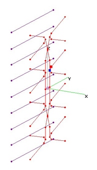
 | 4.
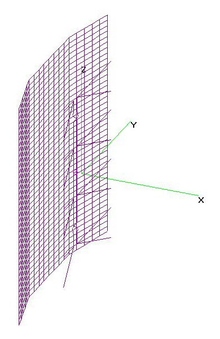
UHF FF4 SingleAngleRefl - DeepSidelobes (25 Jun 2015)UHF Free-Form 4-Bay (FF4) with Single Angle Reflector providing Deep Sidelobes on lower Frequencies
was analyzed using 4nec2.
I haven't (yet) figured out how to use nikiml's Optimizer to minimize Gain on one Azimuthal Angle while ALSO
maximizing Gain in the Forward direction (if it is even possible), so the fol. might not be an "Optimum" solution.
I MANUALLY tried a bunch of things for FF4 with Double and Single Angle Reflectors. I ended up with the fol. TWO
designs which have VERY DEEP SIDELOBES on 470 MHz (at 45-deg away from Forward), which decreases in depth
on the higher frequencies. Raw Gain also drops off on the higher frequencies. The key was to decrease the
Reflector Sweep to only 2-inches.
==================================
a) The first alternative started with FF4+VSAR, where ALL Variables were Optimized, including the Reflector
Bend Depth (i.e. Angle) and THEN manually varying the Bend Depth for best Sidelobe on 470 MHz: Gain in
the Null is -16.9 dB and 30-deg away from the Null the Gain is 12.6 dB, for a TOTAL Suppression of 29.8 dB.
However there is significant Loss on higher UHF Channels, accompanied by a reduction in Sidelobe Depth.
====================================
b) The second alternative started with the 2-in Bend Depth determined above and then Re-Optimized the remaining
Variables to Maximize Gain throughout the UHF Band. This resulted in Deep Sidelobe Nulls all across the UHF Band.
UHF Raw Gain = 14.2 to 17.3 dBi, F/B & F/R Ratio Min. = 15.7 dB and SWR (300-ohms) under 2.3.
It is possible that a more exhaustive search could uncover a somewhat "better" alignment...
PS: For some unknown reason, I was unable to generate Hi-VHF Band Performance using either 4nec2 or
nikiml's EVAL function....but it's probably similar to alternative (a) due to similarity of Dimensions.
ADJUSTING REFLECTOR BEND DEPTH TO MOVE FREQUENCY OF MAX NULL DEPTH[/COLOR][/B]
The Bend Depth in the above FF4+VSAR can be adjusted to move the Max Null Depth to the desired Channel
Frequency, as shown in the fol. table. If even deeper Nulls are needed in the upper frequency band,
the FF4 would need to be Re-Optimized with this in mind:
Reflector Bend Depth is the difference between the X-Coord locations at the Center and the Outer Edges.
FF4+VSAR: SIDELOBE NULL RAW GAIN & ANGLE AWAY FROM MAX BEAM,
For Various Reflector BEND DEPTHS:
FREQ: 470 530 590 650 698 758 806 MHz
BEND:
1.0-in -16.7 -10.4 -3.9 -0.6 1.8 1.8 4.6 dBi
45-deg 40-deg 35-deg 35-deg 30-deg 25-deg 20-deg
1.5-in -10.6 -20.5 -7.1 -2.7 0.8 0.6 4.0 dBi
45-deg 40-deg 35-deg 30-deg 30-deg 25-deg 20-deg
2.0-in -7.0 -21.2 -7.1 -2.7 1.5 -1.6 4.0 dBi
40-deg 40-deg 35-deg 30-deg 30-deg 25-deg 25-deg
2.5-in -4.4 -13.3 -18.9 -10.7 -0.7 -2.2 2.2 dBi
45-deg 40-deg 35-deg 30-deg 25-deg 25-deg 20-deg
3.0-in -2.3 -8.4 -16.4 -18.4 -2.9 -3.7 -0.9 dBi
45-deg 40-deg 35-deg 30-deg 25-deg 25-deg 20-deg
3.5-in -0.6 -5.3 -10.3 -16.3 -5.2 -5.3 -0.7 dBi
45-deg 40-deg 35-deg 30-deg 25-deg 25-deg 20-deg
4.0-in -0.8 -3.0 -6.6 -10.1 -7.2 -6.8 -2.6 dBi
45-deg 40-deg 35-deg 30-deg 25-deg 25-deg 20-deg
EDIT (17Jul2015): Added Second Alternative, with Good Frequency Response and Deep Sidelobe Nulls
all across UHF Band (470-698 MHz).
EDIT (20Jul2015): Added Null Depth Gain vs Reflector Bend Depth Chart. |
| 3181 Visits
36 Items
Gallery Album | |
|
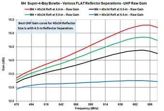
 | 5.
UHF M4 (10x9.5) Super-4-Bay+DAR (16 Oct 2011)mclapp's M4 (10"x9.5") Super-4-Bay Bowtie with 2-in Swept Forward Bowties and Double Angled Reflector analyzed using 4nec2.
Same Reflector as for M4 (9.5"x9"). Dimensions found here: http://m4antenna.eastmasonvilleweather.com/index.html
Performance in New UHF Band, esp. lower channels, is slightly better than M4 (9.5"x9").
Website re DIY Construction: https://sites.google.com/site/maycreates/ota-setup/mclapp-4
UHF Raw Gain = 13.8 to 15.8 to 15.0 dBi, F/B & F/R Min = 18.2 dB and SWR (300-ohms) under 2.2.
Hi-VHF Raw Gain = 9.5 to 9.0 dBi, F/B & F/R Ratio = 12 to 19 dB [FAIR-GOOD] and
SWR (300-ohms) = 6 to 16 [EXCESSIVE].
AWG8 BowLength = 10.0-in, Bowtie Spacing = 9.5-in, Bowtie Forward Sweep= 2.0, Tine Separation = 5.5-in.
AWG12 Feedline Separation = 1.25-in, with 1.0-in at Crossover. Center of Crossover 3.125-in from Center of Outer Bowties.
Double Angled Screen Reflector, 16-Gauge, 40"Hx36"W, with outer 10-in bent forward 2.5-in, Grid = 1"H x 2"W.
Separation of Reflector from Bowties=4.5-in (at centerline).
Gain and SWR are Good for entire New UHF Band, with only moderate reduction for Old Band (Ch52-69).
Hi-VHF Ch7-13 has only moderate Net Gain loss due to increasing SWR on Ch9-13. |
| 8860 Visits
19 Items
Shared Album | |
|
 | 6.
UHF M4 (9.5x9.0)+DAR Flat vs Swept Bows (18 Mar 2010)mclapp M4 Super-4-Bay (9.5x9.0) with FLAT vs SWEPT Bowties and Double Angled Reflector analyzed to
determine Optimum Forward Sweep (BowSwp=2.0-in), presuming all dimensions per
mclapp's posted drawings, as optimized for New UHF Band (Ch14-51), using 1/8-in = AWG8 elements
and AWG12 feedlines: http://m4antenna.eastmasonvilleweather.com/index.html
Website re DIY Construction: https://sites.google.com/site/maycreates/ota-setup/mclapp-4
UHF Raw Gain = 13.3 to 15.8 dBi, F/B & F/R Min = 19.3 dB [EXCL] and SWR (300-ohms) under 2.8.
Hi-VHF Raw Gain = 8.3 to 8.6 dBi, F/B & F/R Ratio = 18 to 22 dB [GOOD-EXCL] and
SWR (300-ohms) = 4 to 15 [EXCESSIVE].
BowLength = 9.5-in (AWG8), Inner-Inner Bowtie Spacing = 9.0-in, Inner-Outer Bowtie Spacing = 9.0,
Tine Separation = 5.5-in. Feedline Separation = 1.25-in (AWG12), with 1.0-in at Crossover.
Center of Crossover 3.125-in from Center of Outer Bowties.
Double Angled Screen Reflector, 16-Gauge, 40"Hx36"W, with outer 10-in bent forward 2.5-in, Grid = 1"H x 2"W.
Separation of Reflector from Bowties=4.5-in (at centerline).
Gain and SWR are Good for entire New UHF Band, with only moderate reduction for Old Band (Ch52-69).
Hi-VHF Ch7-13 has only moderate Net Gain loss due to increasing SWR on Ch9-13. |
| 6231 Visits
33 Items
Shared Album | |
|
 | 7.
M4 (9.5x9.0)+DAR Flat v Swept Bows (13 Apr 2010)All AWG10 mclapp M4 4-Bay (9.5x9.0) with FLAT vs SWEPT Bowties and Double Angled Reflector analyzed to determine
Optimum Forward Sweep (BowSwp=1.0-in), presuming the use of AWG10 for ALL elements and feedlines.
mclapp's M4 (9-5x9) Super-4-Bay Bowtie, with Angled Reflector, optimized for New UHF Band (Ch14-51):
http://www.frontiernet.net/~mclapp/Antennas/diagrams.html
http://www.frontiernet.net/~mclapp/Antennas/4baystuff/4%20bay%20angled%20reflector.pdf
FYI: Performance comparisons (With Reflectors):
http://www.frontiernet.net/~mclapp/Antennas/plots/Antenna%20plots%20with%20reflectors%20UHF.gif
http://www.frontiernet.net/~mclapp/Antennas/plots/4%20bay%20compare11-23-08.xls
BowLength = 9.5-in, Inner-Inner Bowtie Spacing = 9.0-in, Inner-Outer Bowtie Spacing = 9.0,
Tine Separation = 5.5-in, Feedline Separation = 1.25-in, with 1.0-in at Crossover.
Double Angled Screen Reflector, 16-Gauge, 40"Hx36"W, with outer 10-in bent forward, Grid = 1"H x 2"W.
Separation of Reflector from Bowties=4.5-in (at centerline).
Gain and SWR are Good for entire New UHF Band, with only moderate reduction for Old Band (Ch52-69).
Optimum Bow Sweep is about 1-in.
Hi-VHF Ch7-8 has moderate Net Gain loss due to increasing SWR, which becomes excessive on Ch9-13.
Although there is minimal Raw Gain on Ch6 and FM Band, SWR is extremely high. |
| 5169 Visits
25 Items
Shared Album | |
|
 | 8.
M4 (9.5x9) + Various FLAT Refl. Widths (27 Nov 2013)M4(9.5x9) Various Flat (40-in H, 2"x4" Grid) Screen Reflector Widths and Reflector-Bowtie
Separations were analyzed using 4nec2 and Parametric Variation of these two Variables.
UHF Gain continues to increase as the Reflector Width Increases, HOWEVER, BEST Hi-VHF Gain
and F/R Ratio Performance requires 32-in Reflector Width. At small Widths, Hi-VHF Gain
will be either more or less SAME toward Front and Rear.....or HIGHER towards the REAR on
Lower Channels. Increasing HEIGHT of the Reflector continues to improve UHF Gain, but fairly
slowly after it extends beyond the Bowtie by a couple inches.
UHF Performance continues to increase as the Reflector Width increses, HOWEVER, BEST Hi-VHF
Gain and F/B Ratio Performance requires a 32-in Reflector Width. At small Widths, Hi-VHF Gain
will be either more or less SAME toward Front and Rear.....or HIGHER towards the REAR on
Lower Channels. |
| 4485 Visits
12 Items
Shared Album | |
|
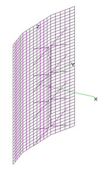
 | 9.
M4 (9.5x9.0) + 40x34 FLAT Refl at 5-in (7 Nov 2013)M4 (9.5x9.0) Super-4-Bay Bowtie (all AWG10) with 40-in H x 34-in W FLAT Screen Grid
(1x2-in) at Various Reflector-To-Bowtie Separations analyzed using 4nec2.
[In previous analysis, 40x34-in Reflector was found to be the "Best" size.]
"Best" UHF Performance is at Separation = 5.0-in, with acceptable SWR Under 2.7
[Max Criteria for low Mis-Match and EVM Loss] with F/B & F/R Ratios over 20 dB.
UHF Raw Gain = 13.3 to 14.9 dBi, F/B & F/R Ratio Min = 19.8 dB and SWR (300-ohms) under 2.7.
Hi-VHF Raw Gain = 8.7 to 8.9 dBi, F/B & F/R = 10 to 16 dB and SWR (300-ohms) = 4.1 to 14.1. |
| 9716 Visits
22 Items
Shared Album | |
|
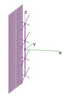 | 10.
UHF M4 (9.5x9.0) 4-Bay+FLAT Grid at 5.5" (27 Oct 2013)UHF M4 (9.5"x9.0") with Flat Screen Grid Reflector analyzed using 4nec2.
Dimensions for Bowties are for mclapp's M4 using AWG8 per his website drawings.
There was no attempt was made here (yet) to jointly optimize Bowtie & Reflector dimensions.
Two versions are presented, the first with a 32-in Reflector Width, the second with
a 28-in Reflector Width. Modeling Results for a wide range of Widths is Charted below:
a) REFLECTOR = 40x32: Flattest Gain across all UHF Channels....and Good for Hi-VHF: 40-in x 32-in Screen Grid
(1"x2") Reflector located 5.5-in behind 4-Bay Bowties.
UHF Raw Gain = 13.1 to 14.5 dBi, F/B & F/R Ratio Min = 20.1 dB and SWR (300-ohms) under 2.5.
Hi-VHF Raw Gain = 8.6 to 8.9 dBi, F/B & F/R = 8 to 14 dB and SWR (300-ohms) = 3.9 to 12.7.
###########################################################
b) REFLECTOR = 40x28: Slightly higher Gain on highest UHF Channels....but loses Gain, F/B & F/R Ratios on lower
Hi-VHF channels: 40-in x 28-in Screen Grid (1"x2") Reflector located 5.5-in behind 4-Bay Bowties.
UHF Raw Gain = 12.8 to 14.7 dBi, F/B & F/R Ratio Min = 18.9 dB and SWR (300-ohms) under 2.5.
Hi-VHF Raw Gain = 7.4 to 8.8 dBi, F/B & F/R = 2 to 10 and SWR (300-ohms) = 5 to 14.
ERRATA (27Oct2013): Corrected labels and narrative (charts remain the same).
Separation between Reflector and Bowties is actually 5.5-in (vice 6.5-in).
When defining the nec file names, I had overlooked -1 inch offset of Bowties. |
| 8816 Visits
42 Items
Shared Album | |
|
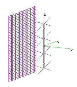 | 11.
UHF M4 (9.5x9.0) 4-Bay+FLAT Grid at 16" (27 Oct 2013)UHF M4 (9.5"x9.0") with Flat Screen Grid Reflector analyzed using 4nec2.
Dimensions for Bowties are for mclapp's M4 using AWG8 per his website drawings.
There was no attempt was made here (yet) to jointly optimize Bowtie & Reflector dimensions.
Better for HiVHF: 40-in x 40-in Screen Grid (1"x2") Reflector located 16-in behind 4-Bay Bowties,
but higher SWR on lowest UHF Channels and Gain on higher UHF channels moves to +/- 25-deg,
resulting in reduced Forward Gain.
[An improved design should be investigated, reducing these UHF degradations.]
UHF Raw Gain = 13.7 to 14.5 to 9.8 dBi, F/B & F/R Ratio Min = 10.9 dB and SWR (300-ohms)
up to 4.5 on Ch14 and under 2.7 on Ch17 and above.
Hi-VHF Raw Gain = 8.0 to 7.7 dBi, F/B & F/R Ratio = 13-15 dB and SWR (300-ohms) under 3.2.
ERRATA (27Oct2013): Corrected labels and narrative (charts remain the same).
Separation between Reflector and Bowties for the two alternatives is actually 16-in (vice 17-in).
When defining nec file names, I overlooked -1 inch offset in the Bowties. |
| 5206 Visits
21 Items
Gallery Album | |
|
 | 12.
M4 (9.5x9) + Various Number of RRs - OPT (26 Nov 2013)M4 (9.5x9.0) 4-Bay Bowtie with Various Number of Reflector Rods (RR) analyzed using 4nec2.
UHF (Only) performance was Optimized using nikiml's Python Scripts to search Length,
Rod-Rod Spacing and Bowtie to Reflector Rod Separation.
As expected, 41RR provided the best overall performance, but 17RR was a close second,
with considerable savings in the cost of metal and wind resistance.
7RRs: UHF Raw Gain = 11.6 to 14.4 dBi, F/B & F/R Ratio Min = 11.9 dB and SWR (300-ohms) Under 2-6.
17RRs: UHF Raw Gain = 12.8 to 15.2 dBi, F/B & F/R Ratio Min = 17.6 dB and SWR (300-ohms) Under 2-6.
41RRs: UHF Raw Gain = 13.3 to 14.8 to 14.7 dBi, F/B & F/R Ratio Min = 21.3 dB and SWR (300-ohms) Under 2-7.
Summary of Optimized Dimensions (in inches, may round off to nearest 0.1 or 1/8-in).
Due to choosing different Min-Max YRod, there were two modes of operation - Narrow and Wide,
where the latter is showing yet another mode of operation change in vicinity of RR=17 to 15.
NARROW SOLUTION DIMENSIONS (see Comparison Charts Below):
Num. RR= 41 31 25 21 17 15 13 9 7 5 3
RS= 5.08 4.99 4.79 4.86 4.76 4.75 4.55 4.59 4.53 4.61 4.28
RR= 1.00 1.33 1.67 2.00 2.50 2.86 3.33 4.00 4.36 6.20 7.41
YRod= 18.84 17.58 17.34 15.18 14.29 13.87 13.55 13.57 13.29 12.62 13.00
WIDE SOLUTION DIMENSIONS:
Num. RR= 41 31 25 21 17 15 13 9 7 5 3
RS= 4.46 4.60 4.88 4.63 4.87 4.91 4.96 4.40 4.12 3.68 3.12
RR= 1.00 1.33 1.67 2.00 2.50 2.31 2.58 3.33 4.15 6.11 6.02
YRod= 22.69 24.64 24.77 24.90 26.54 17.03 16.24 18.13 18.20 18.20 18.08
All Rrod=0.125-in Radius, RS = Reflector-to-Bowtie Separation, RR = Rod-to-Rod
Separation, YRod = Half-Length of Reflector Rods.]
EDIT (2Jan2014): Split out YRod = Narrow and Wide solutions in summary, Charts show
Wide for RR=31-21 and Narrow for the rest and still need to be updated.
EDIT (8Jan2014): Added entries in Wide Solution Chart and (Narrow) Comparison Charts. |
| 4262 Visits
17 Items
Shared Album | |
|
 | 13.
UHF KosmicSuperQuad+DAR FlatvsSwept Bows (18 Mar 2010)Kosmic Super-Quad 4-Bay (9.75x9.5) with FLAT vs SWEPT Bowties and Single Angled Reflector analyzed using 4nec2 to find Optimum Forward Sweep.
Dimensions obtained from EscapeVelocity's original post:
http://www.dtvusaforum.com/dtv-hdtv-reception-antenna-discussion/8629-kosmic-antennas-superquad-4-bay-bowtie.html
AWG9 BowLength = 9.75-in, Bowtie Spacing = 9.5-in, Tine Separation = 5.0-in. Simulated SOURCE wire.
AWG9 Feedline Separation = 1.5-in, except 1.25 at Crossovers. Crossovers = 4.75-in from Outer Bowties.
Angled Screen Reflector 34"H x 28"W, with outer 2-in bent forward and center is 4.75-in from Bowties (Grid = 1"H x 2"W).
Optimum Forward Sweep for Full UHF Band Gain is now about 3-in, whereas
Optimum for New UHF Band is about 2-in...although differences are small.....
But best F/B and F/R Ratios are provided when BowSwp is minimized,
so it's a counterproductive tradeoff of whether you want to squeeze out a few
fractions of a dB in Gain whilst losing several dB in F/B & F/R Ratio....
So if F/B & F/R are important in a given location, use BowSwp=1.0-in. |
| 3887 Visits
21 Items
Shared Album | |
|
 | 14.
UHF Actual CM4221 Flat Bows & Reflector (27Aug2009)Channel Master CM4221 4-Bay (8.5x8.9) Bowtie Antenna (with Reflector Screen) analyzed using 4nec2.
Measurements verified against a photo posted by mclapp:
http://www.frontiernet.net/~mclapp/Antennas/CM4221/CM4221%20front.jpg
BowLength = 8.5-in, Bowtie Spacing = 8.9-in, Tine Separation = 5.25-in. All AWG8.
Feedline Separation = 1.4-in, with 0.8-in at Crossover. All AWG8 wire size (0.125" O.D.).
Center of Crossovers 2.75-in from Center of Outer Bowties.
Screen Reflector (36"H x 20"W). Separation from Bowties = 4.5-in.
Gain increases from 12.2 to 14.9 dBi at 698 MHz. SWR is mostly under 2.0, climbing as high
as 3.3 at 470 MHz, which results in minor Net Gain loss at Low Freqs.
If the Crossovers were moved from their current location (2.75-in away from Outer Bowties),
so that they are Centered between the Bowties (as is done in some UTube 4-Bays), the Gain
at the highest frequencies is significantly reduced with about a 1 dB loss in F/B Ratio. The SWR
at Low Freqs also increases, resulting in an additional 1 dB Net Gain loss at 470 MHz.
Results for Ken Nist's CM4221a.ez file are also included in the comparison Charts, showing minor Raw Gain
loss vs the ACTUAL CM4221, higher SWR (reducing Net Gain at low freqs) and a higher F/B Ratio. |
| 7492 Visits
17 Items
Shared Album | |
|
 | 15.
UHF CM4221a.ez.nec Flat Bows & Reflector (17 Aug2009)Channel Master CM4221 4-Bay (7.8x8.0) Bowtie (Ken Nist's cm4221a.ez file) with Screen Reflector analyzed using 4nec2.
It appears that Ken Nist simply took HALF of the CM4228a.ez file, as evidenced by the off-set axis.
BowLength = 7.8-in, Bowtie Spacing = 8-in, Tine Separation = 5.5-in.
Feedline Separation = 1.25-in, with 0.8-in at Crossover.
Center of Crossovers 4.0-in from Center of Outer Bowties.
Screen Reflector (36"H x 20"W). Separation from Bowties = 4.5-in.
FWIW: Measurements on an ACTUAL CM4221 antenna were somewhat different. |
| 6343 Visits
11 Items
Shared Album | |
|
 | 16.
UHF CM4221HD (Hacked) - 16 ReflRods (5 Oct 2011)UHF (New) CM4221HD 4-Bay with 16 Reflector Rods (23.6-in Wide, Sep=4.25-in) modeled using 4nec2.
UHF Raw Gain=11.2-14.8 dBi. UHF SWR(300) under 2.1.
UHF F/B Ratio=19-33 dB and UHF F/R Ratio=15-18 dB.
NOTE: CM4221HD's PCB Balun ATTENUATES VHF, however if REPLACE Balun then:
Hi-VHF Raw Gain=3-6.6 dBi (FORWARD), but HIGHER Hi-VHF Raw Gain=7.7-5.0 dBi (TOWARDS REAR!).
Hi-VHF SWR(300)=EXCESSIVE, esp. on lower Hi-VHF channels.
CM4221HD measurements per fol. smpowell55 posts:
http://www.digitalhome.ca/forum/showthread.php?p=863127
http://www.digitalhome.ca/forum/showthread.php?p=863559
BowLength = 7.9-in, Inner-Inner Bowtie Spacing = 9.84-in, Outer-Inner Bowtie Spacing = 8.46-in,
Tine Separation = 3.94-in. Feedline Separation = 1.18-in, with 0.8-in at Crossover (2" from Outer Bowtie).
16 Rod Reflectors: 23.6" Long with 1.93" Spacings for Total Height = 30-in. Separation from Bowties = 4.25-in.
It is presumed that anyone interested enough to view this webpage will
implement the "Hacked Balun" modifications per photo in fol. rabbit73 post
(flip over the Feedlines going into the Balun plus an additional offset):
http://www.digitalhome.ca/forum/showthread.php?p=1167870
Although NEW, the CM4221HD is still optimized for the OLD UHF Band (up thru Ch69), wasting the Max Gain peak
on channels that are no longer available for DTV. UHF Raw Gain is about the same as older CM4221 with
improved UHF SWR on the lower channels....and Hi-VHF Raw Gain & SWR, such as it is, has been degraded....
Super-Sized-4-Bays have better Gain on New UHF Band (up thru Ch51) and don't have a Hi-VHF Gain Reversal problem.
EDIT (30Mar2013): Added (Slides 7-12) MOSTLY NORMAL plots versus Bowtie Tine Separation and
Bowtie Forward Sweep, although at more than 1-1/2 inch increase in Tine Separation, a significant
Gain & SWR Glitch was found, which could frustrate finding an "Optimum" set of dimensions.
This may or may not be a 4nec2 Modeling anomaly, and might not be inherent in CM4221HD design.
Note that in 8-Bay Bowtie Antennas significant Gain & SWR glitches were found with very small
(under 0.5-in) changes in Tine Separation and Bowtie Forward Sweep from "As Built" dimensions.
EDIT (26Oct2013): Investigated comment below. Segmentation in Feedline etc is as it should be.
However, when investigating other Autoseg numbers other than 11, I found that Autoseg(15)
and Autoseg(21) found "sharp angle warnings" and an AGT error resulting in 1 db lower Gain.
Since the Autoseg(11) did not find any "sharp angle warnings" and looks good, I'm sticking with it.
EDIT (26Oct2013): Added Rmax Parameter Sweep Charts (Reflector Rod Length = 2*Rmax) at 3 freqs.
Rmax can only be increased from 11.8 to 12.8-in before there is Gain LOSS on 698 MHz.
This mod would only result in a very minor (0.05 to 0.3 dB) improvement in overall Gain.
EDIT (3Apr2017): Added Elevation Angle Pattern Charts, showing NULLS at about 30-deg. |
| 9612 Visits
36 Items
Shared Album | |
|
 | 17.
UHF CM-4221HD - 10-in Whiskers (26 Oct 2013)UHF CM4221HD 4-Bat Bowtie (Hacked) + 16 Reflector Rods, modified Whisker Lengths from 7.9-in to 10.0-in.
UHF Raw Gain = 12.2 to 15.4 dBi with SWR under 2.6. Only 1.0 to 0.5 dB IMPROVEMENT to UHF Raw Gain,
and significantly reduces F/B and especially F/R Ratios.
Hi-VHF Raw Gain is 7 to 8 dBi, except lower on Ch12...but to REAR on Ch7-11 and FORWARD on Ch13. |
| 4814 Visits
24 Items
Shared Album | |
|
 | 18.
UHF CM4221HD (Hacked) + Director Rods (17 Jul 2013)UHF CM-4221HD 4-Bay Bowtie with Flat Reflector Screen (As Delivered), with Balun Reversal Hack,
analyzed using 4nec2 after ADDING 1, 2, 3 and then 4 Director Rods in front of each Bowtie,
Optimizing DirRod Lengths and X-Axis placements using nikiml's Python Scripts.
This exercise illustrates the FUTILITY of adding Yagi type Director Rods to Multiple Bowtie
type antennas to improve Raw Gain. A larger Reflector should increase Raw Gain, F/R & F/B Ratios. |
| 4821 Visits
18 Items
Shared Album | |
|
 | 19.
CM4221HD (Hacked) + Stub Filter (18 Dec 2013)UHF (New) CM4221HD 4-Bay with 16 Reflector Rods (23.6-in Wide, Sep=4.25-in) plus
Stub Filter analyzed using 4nec2. The Stub Filter was isolated from the Antenna and the
load (presumed to be a Preamp) by additional transmission lines of the same Length
as the Stub, because connecting Stub Filter directly to Antenna's Feedpoint caused problems.
Two Stub Filters are analyzed, the first with a Half-Wave Length, which is reportedly
"easier to control". The second is the more commonly encountered Quarter-Wave Length:
http://www.eham.net/ehamforum/smf/index.php?topic=17118.0;wap2
http://www.arcticpeak.com/antennapages/quaterwavestub.htm
http://www.onlineconversion.com/frequency_wavelength.htm [Wavelength Calculator]
a) Half-Wave Length Stub Filter with SHORTED End: A Length of 12-in (Notch on 492 MHz)
was chosen to pass Ch14, while attenuating Ch15...which turned out to be fairly minimal,
and completely ruined SWR Characteristics across ENTIRE UHF Band....so NOT very useful.
b) Quarter-Wave Length Stub Filter with OPEN End: A Length of 6.15-in (Notch on 496 MHz)
was chosen with even worse results. Gain was greatly reduced on Ch14 with only minimal
additional reduction on Ch15 and SWR was completely ruined across entire UHF Band.
MORE RUNS PLANNED: Use Simulated Transmission Lines to see if better impedance matching helps. |
| 3919 Visits
30 Items
Shared Album | |
|
 | 20.
Antennacraft U-4000 - 9 Reflector Rods (9 Jun 2013)UHF Antennacraft U-4000 4-Bay Bowtie with 9 Reflector Rods (RR) analyzed using 4nec2.
Based on a 4nec2 file posted by user 300ohm.
Whisker Length=8.0-in, BowInner-Inner=BowInner-Outer=8.0-in, Tine Separation=5.75-in,
Feedline Separation=2.0-in, Hop=0.6-in.
Nine Reflector Rods: Length=20.0-in, Rod-Rod Sep.=3.875-in, Total Height=31-in.
UHF Raw Gain = 9 to 14 dBi, F/B & F/R Ratio Min. = 13.5 dB and SWR (300-ohms) under 5.1 is EXCESSIVE.
Hi-VHF Raw Gain FORWARD = 2.3 to 0.4 to 0.8 dBi and Raw Gain to REAR = 5.8 to 7.5 dBi is HIGHER
and SWR (300-ohms) = 100 to 5.5 is EXCESSIVE. |
| 4631 Visits
21 Items
Shared Album | |
|
 | 21.
A-D Old DB-4 4-Bay Bowtie with Reflector (11 Dec 2011)Antennas Direct (Old ) DB-4 4-Bay Bowtie with Reflector analyzed using 4nec2.
Dimensions per mclapp's 4nec2 file with holl_ands modifications to adjust AGT=1 and various FR & RP statements:
http://www.frontiernet.net/~mclapp/Antennas/Computer%20Models/
Whisker Length=6.17-in, BowInner-Inner=7.85-in, BowInner-Outer=7.9-in, Tine Separation=1.2-in,
Feedline Separation=1.8-in, Hop=1.0-in. Two Reflectors: 12.7"x18.9" at Reflector-to-Bowtie Separation=4-in.
Raw Gain falls off on lowest frequencies. High SWR on low and mid frequencies.
NOTE: d510d180's parameterized 4nec2 model for the DB-4 can be found here (using variable SYmbols):
http://www.avsforum.com/avs-vb/showthread.php?p=15782728 |
| 5359 Visits
20 Items
Shared Album | |
| |
