Offset Crossed Dipoles
Offset Crossed Dipoles, with Quarter-Wavelength separation between Horizontal and Vertical Dipoles
analyzed using 4nec2.
When Right Hand Circular Polarized signals are transmitted, a RHCP Antenna SHOULD
suppress LHCP (multipath) signals, since rotation changes upon reflection from buildings, bridges & terrain.
Offset-Crossed Folded Dipoles (FD) with Quarter-Wavelength separation between the FD's had the best
suppression of Left Hand Circular Polarization (LHCP) relative to Right Hand (RHCP).
A single Transmission Feedline (e.g. twinlead), a Half-Wavelength long interconnecting the two
Folded Dipoles is preferred, compared to two HWL long TL's due primarily to the simpler construction
and a slightly better SWR. Open wire twin-lead with 600-ohms (preferred) or 450-ohms ladder line
should be used, avoiding 300-ohms since it degrades both Gain and SWR:
http://www.gameangler.eu/delboy/m0dad/homebrew_ladder_line.htm
http://www.thewireman.com/antennap.html#balanced
For Crossed Dipoles (75-ohms) use a 93-ohms Coax for the Transmission Line, shortened
as necessary to provide the requisite ELECTRICAL length due to the velocity factor.
Fol. summarizes "typical" velocity factors, BUT check cable specs, many deviate from "typical":
http://www.febo.com/reference/cable_data.html
Date(s): 3 Feb 2011. 1 - 5 of 5 Total. Shared |
|
 | 1.
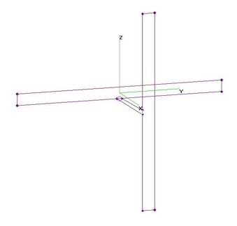
Hi-VHF Offset-Crossed FD's - TL=HWL (21 Jan 2012)Hi-VHF Offset-Crossed Folded Dipoles (FD's) with Quarter-Wavelength offset between the FD's
and HALF-Wavelength Transmission Line (simulated by TL Card) interconnecting the two FD's.
This results in requisite 90-deg difference in signals arriving from each Folded Dipole for RHCP
(Right Hand Circular Polarization).
Optimum TL is 600-ohm Impedance, although 450-ohm may also be used with minor degradation
to Gain and SWR. [In diagrams below, Feedline is NOT TO SCALE.]
With Quarter-Inch Copper Tubing (QICT), 2-in FD "Width" (distance between FD Elements)
and Quarter-Wavelength Separation between the Crossed FD's, a large Gain and SWR GLITCH
was found in the middle of the Hi-VHF Band, the placement depending on the overall FD Length:
189 MHz if 30-in, 202 MHz if 28-in, 210 MHz if 27-in, etc.
If the length of the Cross-FDs are much longer or shorter than when used alone, the GLITCHES
can be moved out-of-band. FD Length = 23-in or 34-in was barely sufficient to avoid the
GLITCHES, as shown below. The longer 34-in FD was better with good RHCP Gain, very good
LHCP suppression characteristics and good SWR.
Note that Right Hand Circular Polarization is strong both FORWARD and REVERSE, but Left Hand
suppression is stronger FORWARD. Reversing one interconnection reverses Polarization, so
VERY CAREFULLY check antenna connections and alignment. Note 20+ dB of LHCP Suppression. |
| 1246 Visits
21 Images
Shared Album | |
|
 | 2.
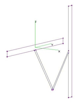
Hi-VHF Offset-Crossed FD's - 2TL=HWL (21 Jan 2012)Hi-VHF Offset-Crossed Folded Dipoles (FD's) with Quarter-Wavelength Separation fed by two Transmission Lines,
each Half-Wavelength Long. This results in requisite 90-deg difference in signals
arriving from each Folded Dipole for RHCP (Right Hand Circular Polarization).
Optimum TL is 600-ohm Impedance, although 450-ohm may also be used with minor degradation
to Gain and SWR. [In diagrams below, Feedlines are NOT TO SCALE.]
With Quarter-Inch Copper Tubing (QICT), 2-in FD "Width" (distance between FD Elements)
and Quarter-Wavelength Separation between the Crossed FD's, a large Gain and SWR GLITCH
was found in the middle of the Hi-VHF Band, the placement depending on the overall FD Length:
189 MHz if 30-in, 202 MHz if 28-in, 209 MHz if 27-in, etc.
If the length of the Cross-FDs are much longer or shorter than when used alone, the GLITCHES
can be moved out-of-band. FD Length = 26-in or 33-in was barely sufficient to avoid the
GLITCHES, as shown below. The longer 34-in FD was better with good RHCP Gain, Excellent
LHCP suppression characteristics and good SWR.
Note that Right Hand Circular Polarization is strong both FORWARD and REVERSE, but Left Hand
suppression is stronger FORWARD. Reversing one interconnection reverses Polarization, so
VERY CAREFULLY check antenna connections and alignment. Note 20+ dB of LHCP Suppression. |
| 1058 Visits
21 Images
Shared Album | |
|
 | 3.
Hi-VHF Offset-Crossed FD's - 2TL=QWL (4 Feb 2012)Hi-VHF Offset-Crossed Folded Dipoles (FD's) with Quarter-Wavelength Separation fed by two Transmission Lines,
each a Quarter-Wavelength Long. This results in requisite 90-deg difference in signals
arriving from each Folded Dipole for RHCP (Right Hand Circular Polarization). |
| 894 Visits
22 Images
Shared Album | |
|
 | 4.
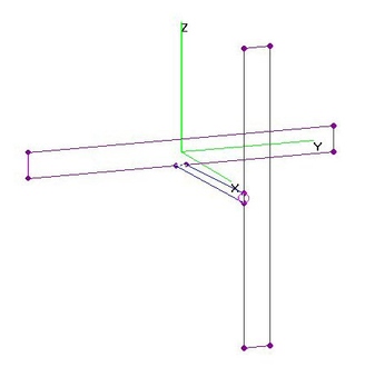
Hi-VHF Offset-Crossed FD's - TL=QWL (21 Jan 2012)Hi-VHF Offset-Crossed Folded Dipoles (FD's) with Quarter-Wavelength offset between the FDs
and Quarter-Wavelength Transmission Line (simulated by TL Card) interconnecting the two FDs.
[In diagrams below, Feedline is NOT TO SCALE.]
[NOTE: Included for illustration purposes only, TL=Half-Wavelength is correct length.]
Optimum TL is 600-ohm Impedance, although 450-ohm may also be used with minor degradation to
Gain and SWR. [NOTE: Velocity Factor MUST be close to 1.0, otherwise electrical length may be too long.]
With Quarter-Inch Copper Tubing (QICT), 2-in FD "Width" (distance between FD Elements)
and Quarter-Wavelength Separation between the Crossed FD's, a large Gain and SWR GLITCH
was found in the middle of the Hi-VHF Band, the placement depending on the overall FD Length:
178 MHz if 32-in, 202 MHz if 28-in, 210 MHz if 27-in, etc.
If the length of the Cross-FDs are much longer or shorter than when used alone, the GLITCHES can be
moved out-of-band. FD Length = 23-in or 34-in was barely sufficient to avoid the GLITCHES, as
shown below. The shorter 23-in FD had better RHCP Gain & LHCP suppression characteristics and better SWR.
Note that Right Hand Circular Polarization is strong both FORWARD and REVERSE, but Left Hand
suppression varies with freq. Reversing one interconnection reverses Polarization,
so VERY CAREFULLY check antenna connections and alignment.
Note Left Hand Circular Polarized (LHCP) signals are suppressed LESS THAN 10 dB relative to Right Hand (RHCP). |
| 988 Visits
21 Images
Shared Album | |
|
 | 5.
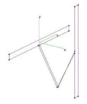
Hi-VHF Offset-Crossed FD's - 2TL=3QWL (21 Jan 2012)Hi-VHF Offset-Crossed Folded Dipoles (FD's) at Quarter-Wavelength Separation fed by two Transmission Lines,
each 3/4-Wavelength long. This results in an imperfect amplitude and phase difference in
signals arriving from each Folded Dipole, degrading RHCP (Right Hand Circular Polarization).
[NOTE: Included for illustration purposes only, TL=Half-Wavelength is correct length.]
Optimum TL is 600-ohm Impedance, although 450-ohm may also be used with minor degradation
to Gain and SWR. [In diagrams below, Feedlines are NOT TO SCALE.]
With Quarter-Inch Copper Tubing (QICT), 2-in FD "Width" (distance between FD Elements)
and Quarter-Wavelength Separation between the Crossed FD's, a large Gain and SWR GLITCH
was found in the middle of the Hi-VHF Band, the placement depending on the overall FD Length:
202 MHz if 28-in, etc.
If the length of the Cross-FDs are much longer or shorter than when used alone, the GLITCHES
can be moved out-of-band. The longer 34-in FD was better with good RHCP Gain, Fair to Good
LHCP suppression characteristics and good SWR.
Note that Right Hand Circular Polarization is strong both FORWARD and REVERSE, but Left Hand
suppression is stronger FORWARD. Reversing one interconnection reverses Polarization, so
VERY CAREFULLY check antenna connections and alignment.
Note Left Hand Circular Polarized (LHCP) signals are suppressed LESS THAN 10 dB relative to Right Hand (RHCP). |
| 1089 Visits
22 Images
Shared Album | |
| |