 | 1.
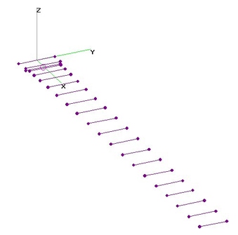
70cm+FRS+GMRS 20-El FD-Yagi (30 Aug 2016)20- Element Folded-Dipole Yagi Antenna to cover entire 70-cm (440 MHz) plus FRS and GMRS Frequency Bands (420 thru 468 MHz) analyzed
using 4nec2 after determining best Dimensions using nikiml's Python Optimization Scripts. Since intended for Transmit Operations, Target SWR
is to be Under 1.6, allowing for OTHER SWR degradations when using a Transmitter that might shut down when SWR reaches 2.0.
TWO ALTERNATIVE DESIGNS ARE PRESENTED:
a) Optimized ONLY for Gain and SWR:
420-468 MHz Raw Gain = 15.7 to 17.0 dBi and SWR (200-ohms) Under 1.3.
######################################
b) Optimized for Gain, SWR, Front/Back and Front/Rear Ratios:
T.B.D. |
| 2157 Visits
18 Images
Shared Album | |
|
 | 2.
2m Stick Vertical Dipole (8 Oct 2015)2-meter Stick Vertical Dipole analyzed using 4nec2.
Raw Gain = 2.05 to 2.13 to 2.22 dBi and SWR (300-ohms) Under 1.44 at 145 MHz
and Under 2.0 from 141 to 150 MHz.
Vertically Polarized Antenna with True OMNI-Directional Response and
minimal Response to Horizontally Polarized signals.
True OMNI, RHCP (Right Hand Circular Polarization) = LHCP (Left Hand Circular
Polarization), so no suppression of Multipath Reflections. |
| 4298 Visits
18 Images
Gallery Album | |
|
 | 3.
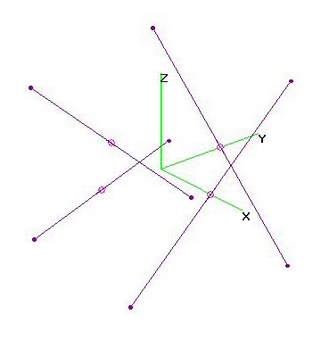
2m Lindenblad Omni Array (7 Oct 2015)2-meter (145 MHz) Lindenblad Omni Array analyzed using 4nec2. More info found here:
http://www.amsat.org/amsat/articles/w6shp/lindy.html
http://www.amphenol-antennas.com/getattachment/e8a306bf-a2ce-412b-a48f-7d55ad509e55/7860xxx.aspx
Based on lindnbld.ez (EZNEC) File downloaded from http://nec-archives.pa3kj.com/EZNEC_FILES,
which was Imported into 4nec2 and then converted into a Variable SYmbol driven File to facilitate
further analysis, as shown below. NONE of the Dimensions have been changed, including Diagonals
being at 46.91-deg (vice 45-deg) Angles.
In this version, separate SOURCEs are used on each Element. In a REAL Antenna, a 4-Way Feedline
would be used, matched to a standard Impedance, and it would likely degrade performance (T.B.D.).
For signals with RHCP (Right Hand Circular Polarization), the Azimuthal Pattern is very OMNI-DIRECTIONAL.
However, for signals with mostly Horizontal Polarization, there is significantly lower Gain.
When signals are Reflected, they usually undergo a change from RHCP to LHCP. This version of the
Lindenblad Omni Array provides a moderate amount of suppression of these Multipath Reflections. |
| 2183 Visits
19 Images
Gallery Album | |
|
 | 4.
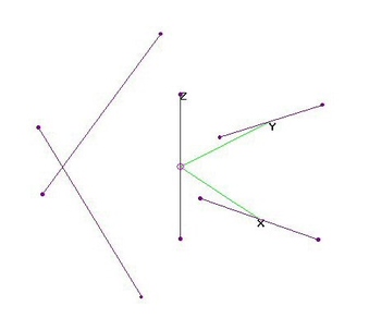
2m Lindenblad Parasitic + Vert. Dipole (7 Oct 2015)2-meter (145 MHz) Lindenblad Parasitic Array with Vertical Dipole Active Element analyzed using 4nec2.
More info found here: http://ww2.amsat.org/wordpress/wp-content/uploads/2014/01/70ParaLindy.pdf
Based on lindnbld.ez (EZNEC) File downloaded from http://nec-archives.pa3kj.com/EZNEC_FILES,
which was Imported into 4nec2 and then converted into a Variable SYmbol driven File to facilitate
further analysis, as found below in the 4nec2 File with Vertical Dipole added.
The Lindenblad PARASITIC Array (with Active Vertical Dipole added in the Center) is SIMILAR to
the Lindenblad Active Array (see analysis in next post). HOWEVER, note that the POSITIVE Angle
of Diagonals in the Lindenblad Active Array must be changed to NEGATIVE Angles in the
Parasitic Array to ensure that it primarily responds to RHCP signals.
Vertical Dipole and Parasitic Diagonal Element Lengths were adjusted for minimum SWR (50-ohms)
and minimum LHCP on 145 MHz, assuming Diagonals at 45-deg Angles and separated 1/4-wavelength
away from the Center of the Antenna (did NOT try to Optimize). All Elements are AWG12 Copper Wire.
For signals with RHCP (Right Hand Circular Polarization), the Azimuthal Patter is TRUE OMNI.
However, for signals with mostly Horizontal Polarization, there is significantly lower Gain.
When signals are reflected, they usually undergo a change from RHCP to LHCP. This version of the
Lindenblad Omni Array provides a moderate amount of suppression of these Multipath Reflections.
Parasitic Elements improve Vertical Dipole's Raw Gain by 0.75 dB to Max = 2.9 dBi at 145 MHz
where Length of Vertical Dipole is adjusted for SWR Min at 145 MHz, while also adjusting Lengths of
Diagonal Parasitic Elements for LHCP Min at 145 MHz.
Response to Horizontally Polarized signals is low but significantly more than Vertical Dipole alone. |
| 4086 Visits
33 Images
Gallery Album | |
| |