 | 1.
UHF Stick Dipole - No Reflector (14 Feb 2011)UHF Stick Dipole analyzed using 4nec2.
Characteristic Impedance of 75-ohms resulted in low SWR near 569 MHz, but Excessive SWR at high and low freqs
in UHF Band. [Note that Folded Dipole has much better SWR vs Frequency.]
Three additional images illustrate a Fair to Good 300-ohms match results if the Dipole Length is 20-percent longer:
Each Whisker=5.27-in with Gap=0.75in for Total WIDTH of 11.29-in, which is a HALF-Wavelength at 523 MHz
(just below middle of the band).
Note that very FAT sticks are needed to minimize SWR throughout the entire UHF Band.
Quarter-Inch-Copper-Tubing (QICT) is analyzed here. (Half-Inch was difficult to model in 4nec2.)
=======================================
Very Wide Band Frequency Sweeps shows FORWARD Gain continues to INCREASE up to about 4.6 dBi at 1425 MHz,
at which point the DIAGONAL Gain in the Clover Leaf Azimuthal Pattern takes over, providing about 2 to 4 dBi up
through about 2700 MHz, at which point a SIX-LOBE Pattern results in Diagonal Gain (varies from 35-deg to 45-deg)
of about 3-4 dBi PLUS Forward Gain of up to about 2 dBi from 3000 to 3500 MHz.
Note that with Characteristic Impedance of 75-ohms, the Stick Dipole is "Resonant" (i.e. Zimag=0) at about 630 MHz
and reaches lowest SWR at not only near 569 MHz in middle of UHF Band, but ALSO near 1775 MHz (3X Higher)
and near 3000 MHz (5.2X Higher). This behavior is how a single set of Elements, e.g. R-S VU Series, can be
designed to cover both Lo-VHF and Hi-VHF Bands. |
| 12394 Visits
34 Items
Shared Album | |
|
 | 2.
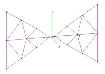
UHF Bowties - NO Reflector (20 Apr 2010)Five UHF Bowtie variations (with NO Reflectors) analyzed using 4nec2. ALL except Solid Triangle are AWG10.
Solid Triangle Bowtie: UHF Raw Gain = 3.4 - 6.3 dBi and SWR (300-ohms) under 2.6 [EXCL].
Six-Whisker Tricon Bowtie: UHF Raw Gain = 3.1 - 5.1 dBi and SWR (300-ohms) under 2.0 [EXCL].
Six-Whisker Bowtie: UHF Raw Gain = 3.4 - 5.0 dBi and SWR (300-ohms) under 2.4 [EXCL].
Four-Whisker Bowtie: UHF Raw Gain = 3.2 - 5.3 dBi and SWR (300-ohms) under 3.0 [FAIR].
Enclosed Bowtie: UHF Raw Gain = 3.8 - 5.4 dBi and SWR (300-ohms) under 3.3 [FAIR].
Indented Bowtie: UHF Raw Gain = 3.6 - 5.5 dBi and SWR (300-ohms) under 4.2 [POOR].
Highest Raw Gain was provided by optimized Solid Triangle, about 1 dB higher on highest freqs.
Flattest Gain was (tie) 6-Whisker & Enclosed Bowtie, latter had Highest Gain on Low Channels.
Optimum dimensions determined by nikiml's Optimization Scripts were Hypotenuse=9.75-in,
Tip-to-Tip Vertical Separation=12-in and Feedline Separation=1.0-in. Hi-VHF analysis is also provided.
Six-Whisker had better SWR (300-ohms) than Four-Whisker version.
Tine Separation is measured between upper and lower Whisker Tips.
Quasi-optimum 6-Whisker sizes for ALL AWG10 wire sizes:
All BowLength=10-in, TineSeparation=5-in and Feedline Separation=1.5in.
Total WIDTH is 21.5-in, which is a ONE-Wavelength at 549 MHz (middle of the band).
Contrast this to a Dipole which has minimum SWR of about 75-ohms closer to a HALF-Wavelength.
All models had AGT=1.0 (no Gain correction) with No Warnings or Errors, except for 6-Whisker Bowtie:
4nec2's Automatic Gain Test (AGT) would not go below 0.41 dB (UHF) and 0.29 dB (Hi-VHF).
Subtract these corrections from 6-Whisker 4nec2 Gain results below.
The 6-Whisker Tri-Conn Bowtie did NOT require any AGT corrections.
EDIT (7Sep2011): Added 4-Whisker, Enclosed and Indented Bowties.
EDIT (20Jun2013): Added Solid Triangle Bowtie using 33-Wire Model using nikiml's Optimization Scripts.
See CM4251 Parabolic+2-Bay+Grid-Reflector analysis for alternative 265-Wire Model.
EDIT (18Jul2014): Added 6-Whisker Bowtie with Tri-Conn (Triple Connector) between Whiskers and the Balun Feedpoint. AGT is much easier to adjust. |
| 36483 Visits
69 Items
Gallery Album | |
|
 | 3.
UHF Fractal Bowtie - No Reflector (21 Jan 2013)UHF 4th Order Sierpinski Arrowhead (Fractal) Bowtie analyzed using 4nec2.
Three feedpoint geometries were analyzed:
1) End-Fed Anti-Symmetric (mirrored on Centerpoint vice Z-Axis) provided best Raw Gain and SWR,
but SWR was excessive on the lower frequencies, limiting the useful bandwidth.
The sharp dive in the (Forward) Gain curve corresponds to when the Azimuthal Pattern changes into a four-leaf clover,
with minimal Forward Gain...also note that Real Part of Impedance, R(ohm), nose dives down to only 25-ohms,
resulting in a very high SWR peak. These severely limit the usable bandwidth.
2) End-Fed Symmetric (mirrored on Z-Axis) had poor Raw Gain and SWR identical to End-Fed Anti-Symetric.
3) Center-Fed Symmetric had poor Raw Gain as well as poor SWR.
These antennas would need to be Rescaled to match the desired operating band since they were very poor matches
for existing UHF Band. SOURCE Wire length should them be varied to obtain best SWR. |
| 12118 Visits
18 Items
Gallery Album | |
|
 | 4.
UHF CM4248 Folded Dipole Bowtie (ONLY) (17 Jan 2012)UHF CM4248 Folded Dipole Bowtie (ONLY) analyzed using 4nec2.
Dimensions from cm4248 4nec2 file posted by 300ohm, derived from Ken Nist's cm4248a.ez file.
Also found in other Channel Master antennas.
CM4248's Bowtie has two rearward facing stubs, the first results are for this "As-Built" configuration.
Note that the stubs are effectively EXTENDING the overall length of the Bowtie Elements, resulting in
a NARROWER Bowtie, which has LOWER Raw Gain than for a Bowtie without the stubs (see next analysis).
Removing the stubs shifted the frequency of operation significantly upwards (see Wideband Charts at bottom),
which was countered by Rescaling LARGER by the factor 1.38, as shown in the second set of results.
This comparison emphasizes the importance of MODELING to determine results,
rather than expecting Wideband Bowties to follow a 1/2-wavelength
or full-wavelength or some other sort of commonly encountered "Design Rule". |
| 14400 Visits
29 Items
Shared Album | |
|
 | 5.
91XG Dipole ONLY & Dipole+First Director (20 Aug 2011)Antennas Direct 91XG (aka XG91) Dipole (ONLY) analyzed using 4nec2. XG91a.nec model originally from Ken Nist on hdtvprimer.com.
Determined Characteristic Impedance was 350-ohms (300-ohm load had nearly the SAME performance).
Dipole plus the closely coupled First Director also analyzed to show effect on Gain, SWR and Characteristic Impedance,
which was improved to 280-ohms (300-ohm load had nearly the SAME performance).
NOTE: There are several variations of the XG91/91XG from different manufacturers.
Carefully check your dimensions against Ken Nist's model...esp. if you think you have a 75-ohm balun. |
| 7848 Visits
30 Items
Shared Album | |
|
 | 6.
UHF Batwing - No Refl & Screen Grid Refl (16 Oct 2014)UHF Batwing Antenna with No Reflector and 16"H x 12"W Screen Grid Reflector analyzed using 4nec2.
Based on 4nec2 files provided by user <300ohm>.
a) UHF Batwing - No Reflector
UHF Raw Gain = 4.6 to 5.6 to 5.1 dBi and SWR (300-ohms) under 2.1
Raw Gain is FLAT to within +/- 0.5 dB with Excellent SWR.
b) UHF Batwing + 16-in H x 12-in W Screen Grid Reflector at 5-in Separation
UHF Raw Gain = 8.9 to 9.2 to 7.3 dBi, F/B & F/R Ratio Min = 12.4 dB and SWR (300-ohms) under 2.8.
Raw Gain drops off about 2 dB on higher frequencies with minimally acceptable SWR.
F/B & F/R Ratios should improve with somewhat larger Reflector and 1-in vice 2-in Spacings
between Horizontal Wires. |
| 10157 Visits
26 Items
Shared Album | |
|
 | 7.
UHF Small Rhombic Stack (6 Feb 2011)| UHF Small Rhombic Stack analyzed using 4nec2. Elements are AWG14: 20-in and 20.25-in long. [AWG10 & AWG12 should be similar.] |
| 9488 Visits
17 Items
Gallery Album | |
|
 | 8.
UHF Double Rhomboid (10 Mar 2010)UHF Double Rhomboid (18.4 ft long by 8.2 ft wide, AWG12) analyzed using 4nec2.
Although the differences were small, "best" value for Termination Resistors was 300-ohms. |
| 13469 Visits
16 Items
Gallery Album | |
|
 | 9.
VHF Stick Dipoles incl Horiz.Rabbit-Ears (24 Nov 2012)VHF Stick Dipoles of various Length Elements (3/8-in Diameter & 1/4-in Rabbit-Ears in Horizontal configuration)
analyzed using 4nec2. Overall-Lengths of the longer Stick Dipoles are typical for VHF/UHF Combo Antenna widths.
Note that when matched to the "natural" dipole impedance of 75-ohms, SWR is very narrowband.
Better wideband performance is found when terminate into 300-ohms. [Raw Gain is unaffected.]
For Ch2 (57 MHz center freq), it's necessary to match a Total Length of 98.5 inches to 75-ohms,
since 300-ohm load yields Excessive SWR. The resultant Antenna has just barely enough
low SWR bandwidth for Ch2 and should be located at least several inches away from nearby
objects, whether metal or not, to prevent detuning the Antenna.
For Ch3, best Total Length would be 86.25-inches, with similar results, when matched
into 75-ohms [direct connect Coax to Center of Dipole].
For the Ch2 & Ch3 narrowband antennas, wire as small as AWG12 provided acceptable SWR
and same Gain as 3/8-in Aluminum. Twinlead with AWG24 not recommended for Ch2-4 due to poor SWR.
Many/most Rabbit-Ear Antennas can not be extended enough to provide acceptable (under 2.7) SWR on Ch2 & Ch3.
"Best" Gain (only 2 dBi) & SWR (Excessive, under 5) for Hi-VHF Band is when Half-Lengths = 14.5-inches.
Impedance Matching Networks in the Rabbit-Ears base can improve on this SWR...unfortunately
manufacturers' don't want to disclose specs....so don't expect much of an improvement....
EDIT (16Jun2013): Added Total Length = 98.5 inches for Ch2, matched to 75-ohms, including an example 4nec2 File.
ERRATA (16Jun2013): Corrected "Half-Lengths" to "Overall-Length" in labels on all except first image,
which correctly uses "Half-Lengths" when describing Rabbit-Ears. |
| 9790 Visits
21 Items
Gallery Album | |
|
 | 10.
Hi-VHF+UHF Stick Dipole - No Reflector (24 Jul 2014)Hi-VHF+UHF Stick Dipole (NO Reflector) analyzed using 4nec2.
Two versions were analyzed:
a) Optimized for Hi-VHF Band,
b) Jointly Optimized for Hi-VHF & UHF Bands, using nikiml's Optimization Python Scripts.
###############################################
a) Optimized for Hi-VHF Band: Overall Length = 28.2-inches, 1/2-in Copper Tubing.
VERY POOR for UHF Band:
Hi-VHF Raw Gain = 1.8 to 2.0 dBi and SWR (75-ohms) Under 2.8. SWR (300-ohms) = 5.3 to 2.5.
UHF Raw Gain = 4.5 dB at 470 MHz, rolling off to below 0 dBi higher than 570 MHz and
SWR (75-ohms) Excessive except Under 2.7 for 555 to 625 MHz.
UHF SWR (300-ohms) about 6 at 470 MHz, decreasing to below 2.7 at 590 MHz and above,
where there is only negative Raw Gain.
###############################################
b) Jointly Optimized for Hi-VHF and UHF Bands: Length = 25.6-inches, 1/2-in Copper Tubing.
VERY POOR for UHF Band.
Hi-VHF Raw Gain = 2.0 to 2.2 dBi and SWR (75-ohms) = 4.9 to 1.4, excessive on lower channels,
while SWR (300-ohms) = 8.0 to 3.5 is even worse.
UHF Raw Gain = 4-5 dBi in lower UHF Band and then rolls off above about 580 MHz,
SWR (75-ohms) Excessive, except under 2.7 from 605 to 698 MHz, where there is only negative Raw Gain.
SWR (300-ohms) Excessive, except under 2.7 from 655 to 698 MHz, where there is only negative Raw Gain. |
| 7445 Visits
36 Items
Gallery Album | |
|
 | 11.
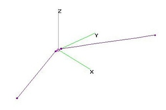
Hi-VHF+UHF "VEE" Stick Dipole (25 Jul 2014)Hi-VHF+UHF "VEE" Stick Dipole (No Reflector) analyzed using 4nec2 after using nikiml's Python Optimization Scripts
to determine the "best" Element Length and Forward Swept Angle to "best" cover BOTH Hi-VHF and UHF Bands.
Hi-VHF Raw Gain = 2.1 to 2.5 dBi and SWR (300-ohms) = 3.0 to 3.3.
UHF Raw Gain = 4.5 to 3.9 to 4.5 to 3.0 dBi and SWR (300-ohms) = 2.0 to 3.6 to 2.6. |
| 7735 Visits
18 Items
Gallery Album | |
|
 | 12.
Hi-VHF Bowties - No Reflector (2 Apr 2010)Hi-VHF Four-Whisker, Six-Whisker, Enclosed and Indented Bowties analyzed using 4nec2.
Performance on Ch2-6 + FMBand was also analyzed. They continue to operate as bi-directional Dipoles with low Gain and much higher SWR on the lower channels.
Six-Whisker Bowtie had better Raw Gain than Four-Whisker and much better SWR than either Four-Whisker, Enclosed or Indented Bowties.
Tine Separation is between upper and lower times.
Raw Gain and Azimuthal Gain Patterns were significantly worse for Enclosed and Indented Bowties. |
| 8562 Visits
61 Items
Gallery Album | |
|
 | 13.
Lo+Hi-VHF 1-Bay Bowtie - No Reflector (24 Nov 2012)Lo-HiVHF (Ch2-13) 1-Bay Bowtie analyzed using 4nec2 after optimizing via nikimil's Python scripts.
NO REFLECTOR RODS:
Ch2-6 Raw Gain = about 3.5 to 5.0 dBi and SWR (300-ohms) Under 2.7.
Ch7-13 Raw Gain = about 4.0 to 5.0 dBi and SWR (300-ohms) Under 2.7.
Provides more Gain than Stick Dipole or Folded Dipole across BOTH Ch2-6 Lo-VHF and Ch7-13 Hi-VHF Bands.
However, narrow beamwidth on Ch7-13 requires careful aiming.
Optimized size is BIG (15.75-ft Wide by 4.25-ft High), using 1/4-in O.D. Copper (may use larger, incl. 3/8-in Aluminum):
Each of Six Whiskers = 92-inches, Top-Bottom Tine Separation = 51-inches & Feedpoint = 5-inches. |
| 7885 Visits
12 Items
Gallery Album | |
| |
