Circular Polarized incl. Rabbit-Ears
Circular Polarized Antennas analyzed using 4nec2.
Circularly Polarized signals are broadcast with a 90-deg phase shift between the Horizontal and Vertical
Polarization components. When Right Hand Circular Polarized signals are transmitted, a RHCP Antenna SHOULD
suppress LHCP (multipath) signals, since rotation changes upon reflection from buildings, bridges & terrain:
http://www.rabbitears.info/oddsandends.php?request=polarization&type=C
Some stations chose to transmit Elliptically Polarized signals, with reduced power in either Horizontal
or (more likely) Vertical component....probably to save money, esp. reducing monthly power bill:
http://www.rabbitears.info/oddsandends.php?request=polarization&type=E
a) Simple Rabbit Ears in "VEE" shape.
b) Goalkeeper Quad-Trapezoid+Spurs
c) Crossed Dipoles.
d) Offset Crossed Dipoles
e) Crossed Yagis
f) Offset Crossed Yagis
g) Helical (Axial-Mode).
h) Circularly Polarized 5-Blade Fan.
FM Cycloid Dipole is also Circular Polarized, providing good suppression of LHCP, but the SWR is very Excessive:
http://imageevent.com/holl_ands/omni/fmcycloiddipole
Date(s): 9 Feb 2001. 1 - 8 of 8 Total. Shared |
|
|
| 1.
Simple "VEE" Rabbit Ears (14 Feb 2011)| Rabbit Ear antennas analyzed using 4nec2. Elliptically Polarized when at 45-degree angle. |
| 2 Albums
Shared Folder | |
|
 | 2.
Hi-VHF Goalkeeper Quad-Trapezoid+Spurs (22 Jul 2014)Hi-VHF Goalkeeper, a Quasi-Omni [accidental] variation of the Quad-Trapezoid+Spurs
was analyzed using 4nec2, assuming QICT (Quarter-Inch Copper Tubing).
Hi-VHF Raw Gain = 2.1 to 2.9 dBi (Forward & Rear) and SWR (300-ohms) under 1.8 (Excellent).
Beamwidth = 100-110 degrees. [For QICT, could substitute AWG10 with higher SWR.]
Provides Bi-Directional Pattern firmly aligned along the X-Axis with wide Beamwidth
and NULLs to the sides. Although Horizontally Polarized, it also provides both
Right-Hand and Left-Hand Circular Polarization, but with only 1 dB LHCP suppression. |
| 5358 Visits
12 Images
Gallery Album | |
| |
| 3.
Crossed Dipoles (5 Feb 2011)Crossed Dipoles analyzed using 4nec2.
When Right Hand Circular Polarized signals are transmitted, a RHCP Antenna SHOULD suppress LHCP
(multipath) signals, since rotation changes upon reflection from buildings, bridges & terrain.
All Crossed Dipoles exhibited POOR Cross Polarization Loss on some Hi-VHF channels and NO LHCP suppression
(of Multipath) from the REAR. Offset-Crossed Folded Dipoles (and Dipoles) performed MUCH better.
K6STI's "Dipole-Pair" (rescaled for Hi-VHF) did not have suffient bandwidth to maintain adequate LHCP suppression
across entire Hi-VHF Band, whether simple Stick Dipole (75-ohms) or Folded Dipole (300-ohms). |
| 4 Albums
Shared Folder | |
| |
| 4.
Offset Crossed Dipoles (3 Feb 2011)Offset Crossed Dipoles, with Quarter-Wavelength separation between Horizontal and Vertical Dipoles
analyzed using 4nec2.
When Right Hand Circular Polarized signals are transmitted, a RHCP Antenna SHOULD
suppress LHCP (multipath) signals, since rotation changes upon reflection from buildings, bridges & terrain.
Offset-Crossed Folded Dipoles (FD) with Quarter-Wavelength separation between the FD's had the best
suppression of Left Hand Circular Polarization (LHCP) relative to Right Hand (RHCP).
A single Transmission Feedline (e.g. twinlead), a Half-Wavelength long interconnecting the two
Folded Dipoles is preferred, compared to two HWL long TL's due primarily to the simpler construction
and a slightly better SWR. Open wire twin-lead with 600-ohms (preferred) or 450-ohms ladder line
should be used, avoiding 300-ohms since it degrades both Gain and SWR:
http://www.gameangler.eu/delboy/m0dad/homebrew_ladder_line.htm
http://www.thewireman.com/antennap.html#balanced
For Crossed Dipoles (75-ohms) use a 93-ohms Coax for the Transmission Line, shortened
as necessary to provide the requisite ELECTRICAL length due to the velocity factor.
Fol. summarizes "typical" velocity factors, BUT check cable specs, many deviate from "typical":
http://www.febo.com/reference/cable_data.html |
| 5 Albums
Shared Folder | |
| |
| 5.
Crossed Yagis (24 Jan 2012)Crossed Yagis analyzed using 4nec2.
Hi-VHF 8-El. Yagi design is from on-line K7MEM calculator:
http://imageevent.com/holl_ands/yagis/hivhf
Since the K7MEM designs are NOT optimized for wide-band use, usable Gain is only
realized on Ch7-10, with reduced F/B and F/R Ratios on Ch7.
ALL of the below K7MEM 8-Element Cross Yagis have POOR and inconsistent
suppression of the Left Hand Circular Polarized (LHCP) signal across the Hi-VHF Band.
Much better LHCP suppression was found in the Offset Crossed Yagis (see other album):
http://imageevent.com/holl_ands/circularpolarized/offsetcrossedyagis
When RHCP signals are reflected (e.g. multipath), it changes to a LHCP signal, which will be
SUPPRESSED by antenna's Cross-Polarization Loss. Hence importance of LHCP suppression,
also known as Cross Polarization Loss (CPL = RHCP - LHCP).
Note that Polarized Gain figures do NOT account for the DOUBLING of Transmitted Power (H+V),
which results in TWICE as high a receive signal power level when RHCP is effective. The 4nec2
program assumes a fixed amount of power input to a "standard" RHCP antenna, which splits
that power into Horiz. and Vert. components. At the receiver, the two components are summed
together via the interconnecting Transmission Line. But DTV uses TWO transmitters.
When/If circular polarization optimization parameters are added to nikiml's optimizations
scripts, re-optimizing the entire antenna might be able to improve on below performance. |
| 3 Albums
Shared Folder | |
| |
| 6.
Offset Crossed Yagis (3 Feb 2011)Offset-Crossed Yagis analyzed using 4nec2, where a Vertically oriented Yagi is mounted
with a Quarter-Wavelength Offset forward of a conventional, Horizontally oriented Yagi.
Hi-VHF 8-El. Yagi design is from on-line K7MEM calculator:
http://imageevent.com/holl_ands/yagis/hivhf
Since the K7MEM designs are NOT optimized for wide-band use, usable Gain is only
realized on Ch7-10, with reduced F/B and F/R Ratios on Ch7.
Much better LHCP suppression was found in K7MEM 8-El. Offset Crossed Yagis than Crossed Yagis:
http://imageevent.com/holl_ands/circularpolarized/crossedyagis
When RHCP signals are reflected (e.g. multipath), it changes to a LHCP signal, which will be
SUPPRESSED by antenna's Cross-Polarization Loss. Hence importance of LHCP suppression,
also known as Cross Polarization Loss (CPL = RHCP - LHCP).
Note that Polarized Gain figures do NOT account for the DOUBLING of Transmitted Power (H+V),
which results in TWICE as high a receive signal power level when RHCP is effective. The 4nec2
program assumes a fixed amount of power input to a "standard" RHCP antenna, which splits
that power into Horiz. and Vert. components. At the receiver, the two components are summed
together via the interconnecting Transmission Line. But DTV uses TWO transmitters.
When/If circular polarization optimization parameters are added to nikiml's optimizations
scripts, re-optimizing the entire antenna might be able to improve on below performance. |
| 7 Albums
Shared Folder | |
| |
| 7.
Helical Circular Polarized (9 Feb 2001)Helical (Axial-Mode) Circularly Polarized (CP) Antennas analyzed using 4nec2 for Hi-VHF Band.
FYI: Some (mostly narrowband) Helical Antenna Design links:
https://www.cv.nrao.edu/~demerson/helixgain/helix.htm [Max Gain Parameter Charts]
http://www.daycounter.com/Calculators/Helical-Antenna-Design-Calculator.phtml
http://www.vk2zay.net/calculators/helical.php
http://scholar.lib.vt.edu/theses/available/etd-120899-112725/unrestricted/etdig.pdf
http://www.antenna-theory.com/antennas/travelling/helix.php |
| 2 Albums
Shared Folder | |
|
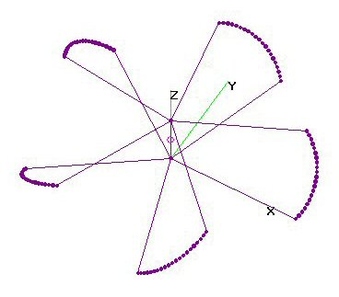 | 8.
UHF Cir-Pol 5-Blade Fan - OPT (29 Aug 2014)UHF Circularly Polarized 5-Blade Fan analyzed using 4nec2. Based design on NomDePlume's
for 1280 MHz Remote Piloted Vehicle (RPV) Band, which I rescaled for UHF Band, see:
http://www.rcgroups.com/forums/showthread.php?t=1389925&page=30
Three versions are presented here, the first a direct Rescale, the second Re-Optimized
to emphasize Horizontal Gain and better SWR with 75-ohm Load and the third an
improved Re-Optimization with wider variable SYmbol search ranges which provided
additional SWR improvement at the expense of reduced Horizontal Gain. |
| 4695 Visits
48 Images
Gallery Album | |
| |