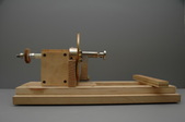
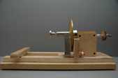
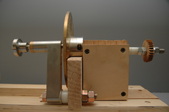
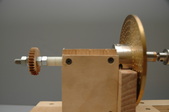
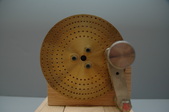
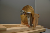
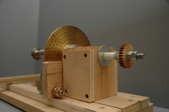
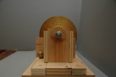
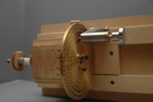
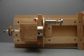
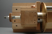
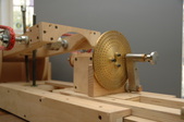
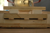
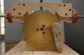
This is the most important and critical machine I had to reconstruct from historical records to be able to cut the wheels' teeth. It is very accurate if set up properly.
Date(s): February 26, 2011. Album by Reid Heilig. 1 - 24 of 52 Total. 2808 Visits.
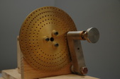
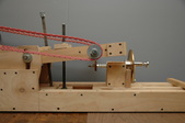
1 Sliding carriage with wheel blank holder and indexing wheel. The horizontal piece on the right of the indexing wheel is the indexing pin that allows one to advance the indexer and then maintain the indexed position. The knob is spring loaded for retraction to rotate the index wheel.
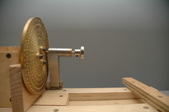
2 Full side on view of indexing wheel and pin, wheel on shaft, and hand hold bar for pushing carriage in and pulling back.
3
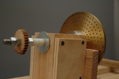
4 Indexing shaft/Wheel blank carriage showing indexing wheel with small mounted wheel that has been toothed.
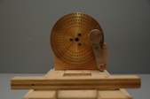
5 Sliding carriage with hand hold for pushing in and pulling out.
6 Idexing wheel showing indexing pin and holes representing the tooth count.
7 Another view.
8 Another view of indexing wheel and pin from the handhold side.
9 Another view.
10
11
12 View of the end that goes first into the saw blade.
13
14
15
16 Wheel blank holder and indexing mechanism inserted into the wheel cutting machine.
17 End view of wheel cutting machine with wheel blank holder inserted in guide ways.
18 End on view showing the clearance between indexing wheel and support arm crosspieces.
19 Fly cutter for cutting wheel teeth. This did not work well. I used a jeweler's slitting saw blade on the rotating shaft to cut all the teeth on my wheels. This was for an experiment and was not as good as the slitting saw method.
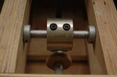
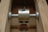
20 Fly cutter showing profile. My problems with this method might lie in the way I made the fly cutter. It was the first one I ever made. I may come back to this later and try to perfect this. Others have had success with this especially in cutting escape wheels.
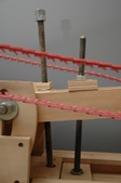
21 Threaded rod shafts that raise or lower the cutter head. It takes 2. I learned the hard way.
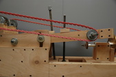
22 Picture showing guide slot for the pivoting of the 2 support arms. There is one on each side.
23
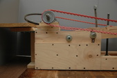
24 Side view showing pivot point and adjusting slot for raising and lowering the two saw blade support arms. This is how the depth of cut is controlled and adjusted. Motor support table is mounted on two leaf hinges with underneath supporting leg for added stability. This allows the changing of saw speed by changing pulley sizes to change their relationship. By having the motor table to pivot freely it allows for some cushioning of motor in the running of the saw blade in wood of varing hardnesses.