1
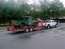
1954 M-37 on the way home in the remains of Hurricane Francis Torrents of rain Sept 09, 2004
| 
2
Shot some paint today to develope a color scheme September 11, 2004. Tommorrow will start a strip down to bare frame. In the future, everything will be blasted with Black Beauty, PPG MP-170 Epoxy Primer and PPG MP-180 Surfacer, then PPG Base/Clear.
| 
3
September 12, 2004, removed winch, nose, engine, tranny, 6 hrs 45 min.
To my surprise, all bolts came loose, nothing had to be torched. Many of the nut/bolts had been coated with Never Seize, even after a long time they spun off.
|
4
September 13, 2004, Blue Wrench Day. Pulled box etc. Many of the large Bolts were rusted from being in the spray. Removed trailer hitch someone built. It was not safe to pull a garden trailer.
| 
5
Spetember 13, 2004. Now to start removal of cab tommorrow.
| 
6
September 14, 2004. Cab just about ready to lift off
|

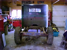
7
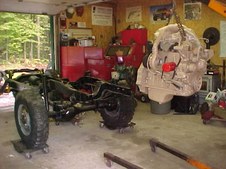
September 14, 2004. First time the frame has seen light in 50 years
| 
8
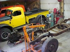
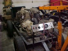
September 14, 2004. The weight of the body/cab surprised me. Its a whole lot heavier than a Power Wagon. Two people could not walk it off the back like we do with PW's. Had to use my Engine hoist to lift it off.
| 
9
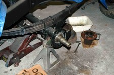
September 14, 2004. Check out the nice safety wire job on the T Case Bolts.
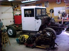
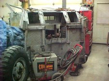
|

10
September 15, 2004
Final strip of frame prior to blasting
| 
11
September 15, 2004
In position, ready for Black Beauty blast of frame.
| 
12
September 15, 2004
Now to find a place for all the parts ??????????????
|
13
September 16, 2004
And on the Seventh Day, I cleaned up and got my shop back in order
| 
14
September 27, 2004
Blasted with Black Beauty, frame is rust free, ready for primer
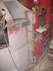
| 
15
September 27, 2004
Frame shot with PPG MP-170 Epoxy Primer
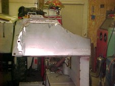
|

16
September 28, 2004
Frame and Disk Brake parts shot with PPG MOA Chassis Black Hardened
| 
17
January 15, 2005
Disk Brakes
| 
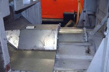
18
January 15, 2005
Front axle Complete
|
19
Front Axle has been totally Zero Timed. All new bearings, races, seals, bronze bushings, helitool disk brakes and 4.89 Ring and Pinions.
| 
20
Along with the Front Axle Rebuild, the steering knuckles were also completely rebuilt. I put the detailed pictures of the knuckle rebuild in its own album #11 titled Knuckle Rebuild.
| 
21
February 27 2005
Springs removed to rebuild bushings, Spring Pin/bolts and add 2 inch lift for the Cummins
|

22
February 27, 2005
Spring Rebuild
| 
23
March 2, 2005
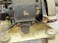
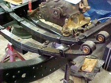
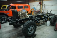
Springs ready to go back on M-37. New NOS Bronze Bushings, 2.000" x 2.000" x 5.500" fabricated steel block under spring to give 2.000" lift for Cummins Engine. This lift block is for measurement purposes ONLY. Lift blocks on Steer Axles are down right DANGEROUS. When complete the lift will be done with changes to the front springs. The T Case is in position for measureing and will be torn down and rebuilt later.
| 
24
March 2, 2005
Waiting for long spring U bolts and this evolution on the rebuild is complete
|
25
March 13, 2005
Left rear disk brakes being installed
| 
26
April 3, 2005
A few minutes here and there during Sugar Season to rebuild the LU-4 Winch. All parts are cleaned and blasted. When complete, I will have a album with pictures and descriptions on total tear down and rebuild of a Braden LU-4 Winch.
| 
27
June 4, 2005
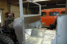
Cab is moved into shop for some repairs and modifications. It will then be Blasted with Black Beauty and Pickle X 20 applied. Then set on frame for measurement with the Cummins 4BTA Diesel
|

28
June 4, 1005
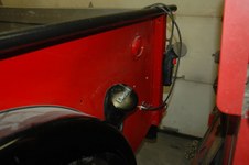
| 
29
June 4, 2005
| 
30
August 8, 2005
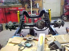
Centered rear axle housing being made ready for install.
|
31
August 27, 2005
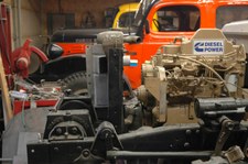
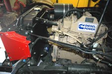
Cummins Recon 4BTA mounted in test fixture. The GM SM-465 is in place only as a rear engine mount. The GM application rotates the engine 7 degrees to the right. When finally installed in the Bandit with a Dodge Transmission, the engine will sit straight.
| 
32
August 27, 2005
Engine will be wired up tomorrow, then to pick up some hoses, Then I can light the oil burner.
| 
33
August 31, 2005
4BTA is running in this picture. She fired right up. WHat a sweet running engine she is !! Now to get her cleaned up and repainted in Cummins Beige.
|

34
August 31, 2005
When the 4BTA is removed from the test fixture, the GM Flywheel Housing, Bell Housing and SM-465 will be removed. The Dodge Drive Line will be installed.
| 
35
September 16, 2005
GM application equipment removed and Engine is in fresh paint
| 
36
September 17, 2005
Dodge Application equipment is added prior to mounting in Bandit
|
37
September 18, 2005
Cummins is on the Hook ready to set in Bandit's frame. Flywheel and Electrics are not installed to save on lift weight
| 
38
September 18, 2005
Front engine mounts fab'ed and installed. Tomorrow I will fab the rear cross member under the NV-4500 which is also the rear engine mount.
| 
39
September 20, 2005
Off the hook and in Bandit. Its amazing what a little Duct Tape and Bailing wire can do.
|

40
September 20, 2005
| 
41
September 20, 2005
When I have the radiator rebuilt, the top radiator connection will be turned down. The lower connection will be changed to a straight outlet. Then 2 short pieces of flex hose to connect the radiator.
| 
42
October 6, 2005
Body/Windshield frame and Bed have been blasted with Fine Black Beauty. It took 11 bags, 7 hours for the cab and 5 hours blasting the bed. Pickle X 20 will now be applied to all steel. Then rusted areas cut out and new steel welded in place. I am planning on repairing the bed first and get it on the frame to free up some shop space.
My Plan is to have repairs done, epoxy primed and underside of bed shot with PPG Chassis Black and sitting on the frame within a week.
|

43
October 9, 2005
Its been a rainy weekend, I got serious and fab'ed two new wheel wells, applied Pickle x-20. primed the bottom with PPG MP-170 Epoxy and then shot PPG MOA Hardened Chassis Black
| 
44
October 9, 2005
Bottom of Bed is complete, ready to put on frame and free up more shop space. The rest of the bed work will be done later this winter
| 
45
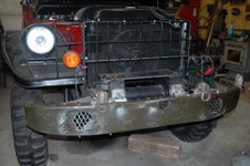
October 9, 2005
The dolly's under the 4 wheels, let me turn Bandit sideways in the shop to load the bed.
|

46
October 9, 2005
Bed is in place on Bandit 7 days ahead of my projected schedule of a week. Next is to do rust repairs on the cab so I can also put it on the frame. This will take longer as fabrication and fitting replacement panels and rocker panels is required.
| 
47
October 04, 2005 (next 3 pictures)
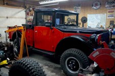
Winter in the North and salt take a toll on sheet metal. Front Qtr Panel is all eaten out, along with rocker panel.
| 
48
Entire area on front left bottom is eaten away by rust. This will all be rebuilt with new steel
|

49
Front Right Qtr Panel eaten by rust as is the Rocker Panel.
| 
50
November 28, 2005
New Rocker Panel is fitted and tacked in place
| 
51
November 28, 2005
Entire bottom left front and cab mount is re-created with new steel. Now to finish weld and then polish the welds and its complete
|

52
November 29, 2005
Front right Qtr Panel being fitted in place, tack welded and finished.
| 
53
November 29, 2005
New Panel in place. Tomorrow I will do some rust repair on the top cowl right above this panel.
| 
54
December 1, 2005
Front Left Qtr Panel installed. No more shore power plug or unsightly knock out plugs on panel.
|
55
December 1, 2005
Its all down hill from here. A few welds to polish off and the shoot the bottom with PPG MP-170 Epoxy Primer and then top coat with PPG MOA Chassis Black Hardened. Once sitting on frame, I will weld up the holes in the cab where the tie downs were mounted. Plans call for the cab to be on the frame by Christmas.
| 
56
December 17, 2005
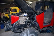
Cab is on in its final position. There is 5.0" clearence between the back of the block and the fire wall and 3.750" between the front and the radiator. With this clearence, I can slide the bed back some and paint everything right on the frame.
| 
57
December 17, 2005
|

58
December 18 2005
The windshield is under modification, top in place and seats set in place for measureing.
My Goal was to be to this point by Christmas. Now I can work my concepts in to final design.
| 
59
December 19, 2005
Cut out the OEM Seat Frame for the Explorer Bucket Seats. Perfect fit, seats will have full range of power motion. Leg angle to Go Pedal will allow Toe'ing the brake from the Go Pedal.
| 
60
December 21, 2005
Left front floor ready to be welded down, Transmission and T Case cover ready for final welding. Tomorrow The right side gets new floor.
|
61
December 23, 2005
Transmission / T Case Cover complete.
Transmission and T Case can now be removed from the top.
| 
62
December 27, 2005
| 
63
December 27, 2005
Cooler holds 12 cans of your favorite beverage. Will cool or heat to 40 degrees above or below outside temperature. It also has an internal battery pack to power it for 4 hours when engine is shut off. In the right rear corner is a
cubby assigned for Col. Colt.
|

64
December 27, 2005
GPS will feed laptop for on screen moving maps on the long trip Bandit is scheduled for once proven.
| 
65
January 6, 2006
Windshield frame in modification for one piece glass. All non essential extra fittings have been removed, including the huge hinge wings on each side.
| 
66
January 11, 2006
Windshield complete and welded down.
|

67
January 29 2006
Cowl Mounted Windshield Wipers Installed
| 
68
February 16, 2005
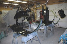
Inside of Cab is now complete. During Sugar Season on slow Sap days I can layout and cut the new dashboard.
| 
69
February 16, 2006
The 66 Caddy Pitman arm fits like a glove. Drag Link is dead bubble level, and when the pitman arm nut is tightened the drag link will be in straight line with the pivot point. The Sweet Mfg Steering U Joint is operating at 4 degrees below max allowed angle.
|

70
February 25, 2006
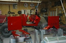
Built in Defrosters wind up the build of the new dash. A NOS Glove Box door is on the way from Sid Beck
| 
71
March 2, 2006
Cab is done, truck turned around on the dollies to now work on Bed.
| 
72
May 21, 2006
Second Fuel Tank being installed. There will also be a lower tool storage and battery box. The two fuel tanks will provide 48 gallons of diesel for a range of roughly 1400 miles.
|

73
Dual Fuel Tank Fills. The Second fill is a stock M37 shortened 6 inches.
| 
74
| 
75
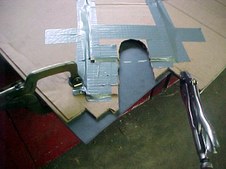
Making a cardboard pattern for the fuel line cutout. Once pattern is taped down to the .125 sheet, its cut with Plasma. The cardboard is not even burned.
|
76
| 
77
| 
78
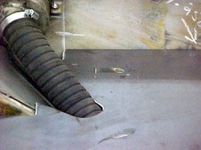
Perfect fit, first shot
|

79
| 
80
| 
81
|

82
June 11, 2006
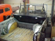
The Bed is now basically complete. Some finish welding and a few dents and dings and she is ready for paint. The 1.00" aluminum tube crossing the box will be sewn into and become part of the roll up Tonneau cover. It will roll up against the cross bed tool box and be retained with two velcro straps.
| 
83
June 14, 2005
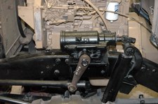
The Winch is a 10,000 pound, worm drive Superwinch Husky 10. The mount will also get a receiver hitch drawbar tube. Tomorrow, I will add some more gussets and the rear suppport. Then a Bumper will be added with built in running lights and roller fairlead. The winch mount only extends 3.875" below the frame rails for good ground clearing.
| 
84
June 16, 2006
The rear bumper is a M37 Front Bumper modified for this job. The running lights and turn signals will be Grote Super Nova LED, the same as I used on the Carryall.
|

85
June 16, 2006
| 
86
June 20, 2006
Access for second tool storage compartment being cut in. Door will match the lower tool box door. Top compartment will also house the ARB compressor for Lockers and Tire Inflation.
| 
87
June 20 2006
Access to Battery compartment being cut in.
|

88
June 21 2006
Tool Box doors complete
| 
89
| 
90
June 22 2006
Battery Compartment Door. Louvers have been added to prevent any possible build up of Hydrogen Gas in the closed compartment
|
91
June 26 2006
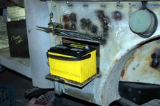
Slide out Battery Tray Complete
| 
92
July 5, 2006
Bed is now off for final prep prior to Paint.
| 
93
July 6 2006
Its the little things that take up so much time. I made two of these fillers right/left. They fit in front of the Cross Box Tool Box, Headache Rack and M37 Bed to allow for gasketing to make it totally water tight. The rear of the Cross Bed Tool Box also has a gasket bar that the Tonneau cover will fasten to to make the rear water tite.
|

94
July 11, 2006
PPG, MP-170 Epoxy Primer
| 
95
July 13, 2006
PPG, MP-182 2K Primer
| 
96
July 13, 2006
All cabinets are shot with Gray Spatter paint with White Flakes. IN the picture is the slide out battery tray compartment
|

97
July 15, 2006
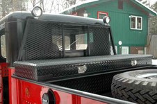
I shot hardened PPG, MOA Black in the bed to provide a good substrate for the Line-X Spray in Liner. The Verticle part of the headache rack will not be shot with Line-X. Line-X would Glop up in the expanded steel and not look good.
| 
98
July 16, 2006
PPG, MBC Red.
| 
99
July 23, 2006
Bed is complete !! I was going to load the bed on my Gooseneck Trailer and take it to have the Bed Line-X'ed. But there is to much chance for damage moving it between trailers. So the bed will get Line-X when the Bandit can drive to Line-X. Now to move on to the Cab.
|

100
New reflectors look great, Thanks Tom
| 
101
| 
102
Second Fuel Tank in its compartment. Compartments are painted with Gray Spatter paint with white flakes and then heavily cleared.
|

103
August 7, 2006
Cab shot with PPG, MP-170 Expoy Prime.
| 
104
August 8, 2006
Cab shot with PPG, MP-182, now the wet sanding.
| 
105
September 03, 2006
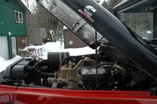
The air induction system. Air is brought in from in front of the radiator. I will fab a air box that will accept a 2003 Ram CTD air filter and then on to the Turbo.
|
106
September 03, 2006
Here you can see the air intake in front of the Radiator and the 3.0" pipe coming out along side the radiator in the engine compartment. This pipe will feed the air box.
| 
107
September 18, 2006
The Laundry is hanging. All parts have been PickleX'ed and now shot with PPG, MP-170 Epoxy Primer. Next will be PPG, MP-182 Primer and finally Color and Clear. Winter is a coming, got to keep moving
| 
108
September 18, 2006
Close up of air induction system. Air enters thru the expanded steel opening, into a cyclone chamber where any large particulate will drop out, then out the 3" pipe to a air box (yet to be fab'ed) and finally into the Turbo on the Cummins
|
109
September 19, 2006
All parts exposed to road spray or the engine compartment have been shot with PPG, MOA Hardened Chassis Black
| 
110
September 26, 2006
PPG, MBC Black top coated with PPG
2060 mixed for a satin finish
| 
111
September 26, 2005
|

112
September 27, 2006
PPG, MBC Red, will be top coated in the morning with PPG High Solids Clear
| 
113
September 28, 2006
All Red shot with PPG MC-161 Clear
| 
114
September 29, 2006
Front end is complete, bed will be lifed on within a few weeks. All that is left is to prep the Arctic Cap and shoot it Satin Black
|

115
September 29, 2006
| 
116
October 7, 2006
Painting is done. The final build will be done this winter
| 
117
October 7, 2006
|

118
October 7, 2006
Can't wait for the first test drive
| 
119
January 10, 2007
Front cover pulled off Cummins to Tab Killer Dowel Pin
| 
120
January 10, 2007
KDP Tab in place along with new front crank seal
|

121
January 14, 2007
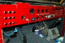
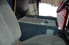
Console nearing completion
| 
122
January 14, 2007
The Ratchet E Brake handle will be here tomorrow. Then I can button up the floor
| 
123
January 14, 2007
|

124
January 14, 2007
Disk E Brake has been fab'ed and installed and 1st Gen Dodge CTD
Muffler installed
| 
125
January 14, 2007
| 
126
January 17, 2007
|

127
January 17, 2007
| 
128
January 23, 2007
Bandit is on External Power getting wired up
| 
129
January 23, 2007
Once all circuits are wired up the gauges will be installed
|

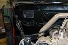
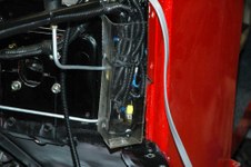
130
January 23, 2007
I am using a 14 volt Current Limit Power supply. Each circuit is run and tested before moving to the next one.
| 
131
January 23, 2007
I am using a 10 circuit load center with a magnetic switch to bring it on line. All heavy current items are switched with relays and all wire is run in loom.
| 
132
January 23, 2007
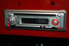
Yup, the tunes are playing. The one song that keeps repeating "Big Sam left Seattle in the year of 91" hmmmm
|
133
January 31, 2007
All wiring is now complete and tested. All that has to be done is install the gages.
| 
134
January 31, 2007
Load Center all buttoned up. Fuse and Relay ID's are on the cover
| 
135
January 31, 2007
Relays for Headlights and Horn
|

136
February 10, 2007
In previous Picture # 24, I had added 2.0" front lift blocks for measurement purposes ONLY. Lift blocks are deadly on a steer axle. The Lift Blocks have now been removed and new springs with 2.0" lift plus added weight capacity for the Cummins have been added. The front spring is a M37 NOS, the Center Spring is the new Spring and the rear spring is the Original M37 with the 2.0" lift block
| 
137
February 10, 2007
Working alone, Everything is cribbed up super kill. I dont want to have a BAD day.
| 
138
February 10, 2007
The new suspension with added lift and carrying capacity are now installed. Kevin at Plattsburgh Spring did the work. I told Kevin I had to have the 2.0" lift. He took NOS M37 front springs and 3 leafs from NOS M37 Rear springs and
made the spring paks. Measured with a ruller the lift is exactly what I had to have 2.0" And the rear shackles are vertical. Thanks Kevin for a great Job.
|

139
March 8, 2007
The fuel tank has been modified for the VDO senders and fuel flow and return lines. The gauge is tested for proper operation before install. Now to do the other fuel tank.
| 
140
March 8, 2007
Fuel tank ready for install.
| 
141
March 9, 2007
The VDO Vision Series Instruments are installed. These instruments have the numbers and lettering ilumenated from behind with fiber optics. The Speedo is driven by a hall effect sensor on either the Tranny or T Case. Its programmable so Differential Ratio or Tire Size can be changed and just reprogram for acurrate speed. It will self calibrate over a measured mile or manually calibrate . Power for illumenation is complete, functions should be hooked up tomorrow.
|
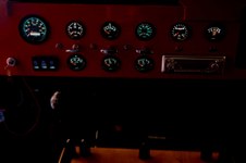
142
March 9 2007
Instruments Illumenated. A few are missing the green filters that were back ordered
| 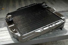
143
May 3 2007
Radiator has been re-cored, water ports moved and changed in size to match the Cummins. Radiator Cores are thru the roof in price, what you see was $701.75
| 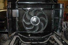
144
May 3, 2007
Electric Fan is in place and expanded steel will harden the entire radiator/fan from rock hits.
|

145
May 3 2007
Expanded steel in place behind grill
| 
146
May 3, 2007
Radiator installed. All that is left is fill with coolent, pre lube the engine, pre lube the turbo and a few loose ends. I may light the oil burner on Sunday.
| 
147
May 5, 2007
Its Alive
Time flies by. I thought the Cummins had been sitting for 11 months without running. I looked at the date on the picture when I took her out of the test frame to mount in the M37....its been 21 months. No wonder this project seems to have taken so long.
This morning, I pre oiled the Cummins, pre oiled the turbo, manually pumped fuel from the new fuel tank to the fuel filter. This is it and hit the key. She started as if she was just shut down and still warm. No cranking, the starter engaged, engine turned over and immediately was running. This is typical for a 4B series good runner.
The Alternator is alternating, the oil burner is a burning, the oil pressure is pressuring, all gauges working, and she sounds sweet. Now its really down hill from here. I'm going out now and start her up, drink a Pepsie and just listen to her run LOL
|

148
May 29, 2007
2nd Fuel Tank complete, ready for fuel. ARB Compressor fits in cubby designed for it.
Hydroboost, JD8 Master Cylinder, Tail Gate, Hella E Code Headlights with Xenon + 50 Burners, Valves for Hydraulic LU-4 Winch ordered today. Its time to get on a roll and
'Git Her Done'.
| 
149
May 29, 2007
Close up of the ARB Compressor installed and tested. All ready to accept air lines from front and rear differentials.
| 
150
June 14, 2007
My Hydroboost Brake system arrived today along with a new 1.3125" Bore Master Cylinder. Also the Solenoid operated high pressure hydraulic valve came that will control the Hydraulically driven LU-4 Winch.
The Hydroboost, Power Steering and Hydraulic LU 4 Winch are all interconnected and will be installed as a Plug and Play package.
The Hydroboost Booster is built to the Power Wagon Spec by Hydratech. In the picture, its designed to bolt right to a Helitool Suspended Pedal assembly, Plug and Play. The Power Wagon Spec Booster works with the Helitool Suspended Pedals in a M37 as well as PW and WC's. For more information and pictures of Hydratech's, Hydroboost Brake system look at the Hydroboost album also at this site.
|

151
June 16, 2007
I was told a few years ago that it was impossible to use Helitool Suspended Pedals in a M37 since the brake pedal was directly inline with the steering column. This is true, but dont believe it cant be done, and simply. To make the brake pedal clear the steering column, you would have to serious bending (re-shapeing) and then the pedal would be shorter in length than the clutch pedal.
Instead and a lot easier is to take the Helitool Suspended Pedals as shipped and just swap the Clutch and Brake pedal. This is plug and play, requiring only a 3/4" wrench to remove the top pivot bolt on each pedal, swap them and re-insert and tighten the pivot bolts. Thats it, problem over.
| 
152
June 16, 2007
Hydratech Inc has developed a Hydroboost Brake unit with a Power Wagon Spec. This spec details the billet machined aluminum mount, Booster Unit and a Plug and Play connection to the Helitool Suspended Pedals. Ten minutes and the Hydroboost is mounted on the Helitool Suspended Pedals. The Master Cylinder in the picture was supplied by Hydroboost, but it is the same one I use on all my trucks NAPA 39017 (Bendix 11584) with a 1.3125" bore (JD-8 option for Hydroboost) The M37 engine compartment gives much more available real estate than a PW or WC. Look at my Carryall or Hydroboost albums to see how close the Hydroboost is on my Carryall compared to the M37 with lots of free space.
| 
153
|
154
June 20, 2007
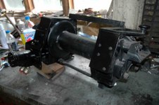
Braden LU-4 Winch now converted to Hydraulic Power with a Char-Lynn Motor.
| 
155
June 22, 2007
High Pressure Electric Valve
| 
156
June 22, 2007
Rear of Electric valve with O ring ports feeding winch
|
157
June 22, 2007
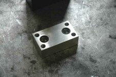
A friend machined this O ringed output manifold to feed winch
| 
158
June 22, 2007
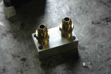
1/2" Pipe to JIC 37 connectors on output manifold
| 
159
June 22, 2007
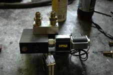
Valve, Output manifold and mount bracket
|
160
June 22, 2007
Assembly complete ready to be fitted in Bandit's engine compartment
| 
161
June 22, 2007
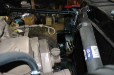
System in place. From the Valve lines will go to the Power Stering and Hydroboost. Other lines will feed the Char-Lynn Motor on the Winch. Tomorrow, I will remove the mount and blast it and paint and reinstall.
| 
162
June 22, 2007
Rear of Valve assembly. The 2 JIC 37 connectors will feed the Char-Lynn Motor on the Winch
|

163
June 22, 2007
Winch and Motor install complete. Tomorrow my 2, 90 degree close street El's will be at NAPA and replace the present ones on the motor. Then I can measure and have all my hoses made and juice the system. I can then check this off the punch list
| 
164
July 4th 2007
Todays Big Bang
The Hydraulic System is complete; Power teering, Hydroboost and LU-4 Winch. The Superwinch Husky 10 Controller will also control the Hydraulic LU-4 Braden Winch. Both winches can be operated locally at the winch or from inside the cab. Milemarker lists the line speed of their 9K Hydraulic Winch as 6.16 FPM, first layer. The Braden Hydraulic LU-4 is has a line speed of 7.250 FPM, first layer. The Winch ran with no cable/load for 30 minutes and the Hoses just got warm, much less than 100 degrees.
Hydraulic Power is not cheap, in fact it cost considerable more than staying shaft drive. But it eliminates PTO's, Drive Shafts, Clearance issues. And the winch is totally independent, I can throw the hook on you at 60 MPH and winch you in.
Now to get ready for a nice BBQ, Parade, Fireworks and ..........................LOL
| 
165
July 9, 2007
Custom front bumper will be fab'ed from an Original M37 non winch bumper. Two days ago, this bumber looked like a Pretzel. I spent a lot of time bending and straightening in my 20 ton H Press. She is good to go now for a driver fun truck. Still a lot of work on her before paint.
|

166
July 11, 2007
The Industrial Grade, Made in USA Fairlead and Cable Tensioner arrived. It has replacable bronze bushings and weighs 24 pounds. Almost ready to blast the bumper and paint.
| 
167
July 17, 2007
Front is now complete. Now to install the Superwinch Husky10 Winch on the rear, bumper, fairlead, lights etc.
| 
168
July 22, 2007
Superwinch Husky 10 Winch controller plug mounted on side of bed. This way I wont have to roll back the bed tonneau cover to access the winch contols.
The same controller also operates the Braden LU-4 Hydraulic Winch when plugged into the front LU-4 controller.
|

169
July 23, 2007
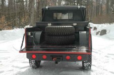
Rear Bumper, Winch, Trailer Plug and Backup Lights all complete. Tail Gate will be painted in a few weeks when I shoot some other parts. I'm Getting closer to roll out LOL
| 
170
December 1, 2007
One Differential complete with 4.89's and ARB Locker. Second differential will be completed tomorrow.
| 
171
December 1, 2007
5 STA Super Lugs mounted, 6th one will be picked up tomorrow. Just in time, one old baloney tire now on Bandit is leaking LOL
|
172
January 25, 2008
| 
173
January 25, 2008
| 
174
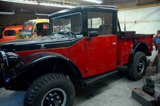
January 26, 2008
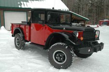
The Bandit is complete and rolls out
|

175
| 
176
| 
177
|

178
| 
179
| 
180
|
181
| 
182
| 
183
|

184
| 
185
| 
186
|

187
| 
188
| 
189
|

190
| 
191
| 
192
|
193
| 
194
| 
195
|

196
| |