 | 1.
Hi-VHF Zig-Zag Build & Attic Install (June 21,2009)Building and Attic Installation for Hi-VHF 14-Element Zig-Zag LPA (Log Periodic Array).
Initially tried to fit the more compact STACKED Zig-Zag configuration....now that we see how much room we have
to play with, will swap in the Risers for an 18-deg WEDGE Zig-Zag configuration. If we can't quite get the
18-deg WEDGE to fit, we'll either reduce the angle or wrap the trapezoid AROUND that pesky stud.
The two trapezoidal 3/4-in Sked 40 PVC frames are held together with press fit (no glue) 90-deg Elbows.
Cross Braces and Risers are attached using 2+ in screws for easy reassembly...and less expensive than PVC.
One trapezoidal frame fits on top of the other, with the Zig-Zag patterns in OPPOSITE directions.
Standard 4:1 (300-to-75-ohm) Balun connects between upper and lower Zig-Zags at small end.
In STACKED configuration, center-to-center height is 3.25-in. Both are 33-in wide and 100-in long.
In WEDGE configuration, widest height separation (between wires) is 31.36-in narrowing down to zero at Balun.
RG-58, RG-59 or equivalent shield coax (0.25 in diameter) is strung in a Zig-Zag pattern within the trapezoids,
using tie-wraps to minimize proximity to (likely) signal sucking PVC.
I stripped insulation off the RG-58, but 4nec2 model revealed it was unnecessary at VHF freqs (but required at UHF).
I would avoid RG-6 type coax unless it has 95+% BRAIDED shield type construction....most are foil + partial braid shield.
Photos show stringing in process, where Balun connects to one Zig and completed Zig-Zags before stacking
and connecting to other side of the Balun. Yes, it takes up most of that big Family Room.
Front & Rear Trapezoid PVC pieces and screws on one end of longest Cross Braces (only...no really) were removed
to collapse and snake through attic access hole (est. 2.5-ft x 2.5-ft)....sorry, we were too busy to take a photo.
The bottom of the WEDGE can lie parallel to the floor and the small elevation angle might even help reception.
Later, we put cardboard boxes under the antenna to keep it away from the signal sucking floor.
Now if those metal nailing plates weren't there....FWIW, inner spirals in black A/C ducts feel like plastic vice metal....
But Deflecto website didn't list the Tele Flow PJ25 Series Flexible Duct....anyone know what's inside????
Current attic location may not be optimal, but avoids looking towards either of two A/C systems or CM-4228.
=============================================================
HOW DOES IT WORK (so far, we aren't done.....):
Although L.A. Ch7 and 9 came in OK, it wouldn't hurt to have more margin....and like many people in L.A.,
we're still waiting for Ch11 and Ch13 to come up to full power....and pending maximization grants to be
implemented sometime in the (near?) future.....
We rotated Stacked Zig-Zag to minimize signals coming from local low power Ch12 (ONLY 2.6 MILES AWAY!!!!)
which can block reception from adjacent Ch11 and 13. Monitoring Ch12 via an analog TV, we needed a WEAK signal,
so bypassed Preamp and went through 25 dB R-S Variable RF Attenuator plus 6 and 10 dB Fixed.
For our situation, we needed about 30 dB.
STACKED Risers were replaced with WEDGE Risers, presumably for another 1-2 dB of Gain and deeper NULL,
but there wasn't enough room to tweak the rotation again....and it was HOT!!!! (110-deg outside)
So we threw the YA-1713 on top of a duct, tweaked it a little and retreated....
Nonetheless, we're still waiting for Ch11 and Ch13 to fix THEIR problems....
============================================================
We also attempted to minimize local Ch27 coming into CM4228, but Ch28 (KCET PBS#3) is simply too weak (NM = 1.8),
so returned to original orientation maximized for Mt. Wilson. New medium gain W-G AP8700 Preamp was better on UHF than
original high gain C-M Spartan...so local stations probably were raising intermod noise floor. [New since original installation.] |
| 3276 Visits
12 Images
Shared Album | |
|
 | 2.
Hi-VHF Stacked ZigZag LPA using RG-59+ (23 Dec 2008)Hi-VHF Band, Stacked Zig-Zag LPA, using Saw-Tooth Wire Elements.
Balun (4:1, 300 to 75-ohm coax transformer) connects between Top and Bottom Zig-Zags at small end (on right).
This version modeled with a simple VERTICAL FEED. SLANT FEED (between outer wire ends) had slightly higher gain (and messy trigonometry).
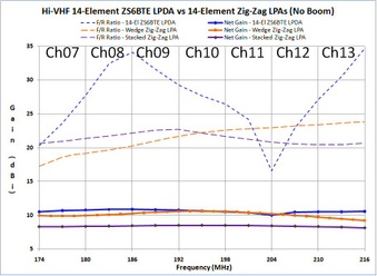
Stacked Zig-Zag has 1-2 dB loss versus SAME Geometry/Construction as a 14-Element LPDA...BUT is much EASIER to construct. |
| 3116 Visits
19 Images
Shared Album | |
|
 | 3.
Hi-VHF Zig-Zag Wedge LPA (No Boom RG-59) (2 Jan 2008)Hi-VHF Band, Zig-Zag Wedge LPA, using Saw-Tooth Wire Elements.
Phi=18 degrees and other variables are optimized for 300-ohm load, using AWG12 or preferably larger wire size,
such as QICT (Quarter Inch Copper Tubing) or Shielded Coax.
Smaller wire sizes have slightly higher SWR and much lower F/B ratios.
Balun (4:1, 300 to 75-ohm coax transformer) connects between two wires connecting Top & Bottom Z-Zs.
See 2nd page for detailed Sweep Plots. Gain is sightly more than LPDA on high channels and slightly less on low. |
| 4365 Visits
26 Images
Shared Album | |
| |