 | 1.
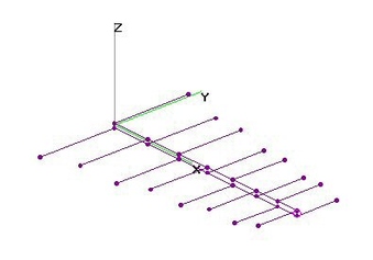
Hi-VHF 7-El LPDA w Shorting Stub (20 Dec 2011)Hi-VHF 7-Element Log Periodic Dipole Array (LPDA) with (and without) Shorting Stub analyzed using 4nec2.
Without the Shorting Stub, performance was significantly degraded.
Hi-VHF Raw Gain = 9.1 to 9.5 to 8.4 dBi, F/B & F/R Ratio MIN = 20 dB and SWR (75-ohms) under 2.3.
Dimensions calculated by LPCAD34, entering Boom Length (48-in), Number of Elements (7),
Rear [= ALL] Element Diameters (3/8-in) and High/Low Frequency Rolloffs (174/216) (see 4nec2 File).
[Other dimensions will generate different results.]
Note that Zig-Zag Transmission Line (TL Card) model does NOT stipulate any Boom Crossection size or shape.
Characteristic Impedance = 75-ohms. LPCAD34 could not calculate a solution for 300-ohms.
LPCAD34 generated a 4nec2 file, but the Shorting Stub was missing the Shorting Wire (GW8), resulting in a
strange attachment off to the side of the front element.
I added a definition of GW8 to the 4nec2 file, with the stub pointed directly upwards from the rear element
to facilitate varying the length and provide easy visibility.
Since LPCAD34 did NOT calculate the requisite Shorting Stub Length, I defined "SLL" as a Symbol variable
and performed an optimization using nikiml's python scripts. Over range of 0.5-15-in, 0.53-in was optimum.
Looking at the charts, it was determined that a more optimized performance was possible if the size
were SMALLER by F=0.98, which reduced SWR and improved F/B & F/R Rations on the highest freq.
Apply this correction to all dimensions in the 4nec2 file. It is already included in below diagrams.
Below LPDA_hiv.doc contains *.bat file for running the scripts, where it was necessary to DISABLE Autosegmentation (OFF=0),
since nikiml's scripts did not properly keep the Transmission Lines (TL Cards) on the middle segments when autosegmenting.
Note that the target-function is a joint optimization of Mismatch-Loss, Gain and Front-To-Rear Ratio.
To increase Gain on higher frequencies, a new design with a 10 to 30-percent larger high frequency rolloff
parameter (FH) should be investigated. |
| 3693 Visits
15 Images
Shared Album | |
|
 | 2.
Hi-VHF 8-El TB-LPDA - NO Shorting Stub (2 Feb 2018)Hi-VHF 8-Element Twin-Boom Log Periodic Dipole Array (TB-LPDA) with NO Shorting Stub analyzed using
4nec2 after finding best TAU-SIGMA Parameters and Dimensions using nikiml's Python Optimization Scripts.
Hi-VHF Raw Gain = 8.7 to 8.5 to 8.8 to 8.7 dBi, F/B & F/R MIN = 26.5 dB and SWR (75-ohms) Under 2.2.
Surprisingly COMPACT: BOOMLENGTH = 46-inches, Max Width = 34-inches.
For the purposes of this 4nec2 model [which doesn't like FAT Wires], 3/8-inch O.D. Booms/Elements was assumed.
However, a 1-in Square Boom and perhaps Fatter Elements is advised for rigidity.
An equivalent 4nec2 Model with a Shorting Stub was ALSO run, but it resulted in a VERY LONG STUB
and made NO DIFFERENCE in Performance, so Results are NOT Presented here.
Note that LPDA's are 75-ohm Impedance (NOT 300-ohms) and hence require the use of a 1:1 Balun,
which is typically fabricated out of some "Quarter-Wavelength" (at 198 MHz) sections of 75-ohm Coax:
http://www.hamradio.me/antennas/coax-velocity-factor.html |
| 569 Visits
16 Images
Shared Album | |
|
 | 3.
Hi-VHF 9-El TB-LPDA with Shorting Stub (4 Feb 2018)Hi-VHF 9-Element Twin-Boom Log Periodic Dipole Array (TB-LPDA) with Shorting Stub analyzed using
4nec2 after finding best TAU-SIGMA Parameters and Dimensions using nikiml's Python Optimization Scripts.
Hi-VHF Raw Gain = 9.1 to 8.8 to 9.2 dBi, F/B & F/R Ratio MIN = 29.5 dB and SWR (75-ohms) Under 2.5.
BOOMLENGTH = 64-inches, Max Width = 34-inches with 2-in Shorting Stub at Rear, which CAN be oriented Down.
Compared to 46-in 8-El LPDA, Boomlength is MUCH LONGER than expected with only 11-in due to L1/L2 Separation.
For the purposes of this 4nec2 model [which doesn't like FAT Wires], 3/8-inch O.D. Booms/Elements was assumed.
However, a 1-in Square Boom and perhaps Fatter Elements is advised for rigidity.
This would lower SWR by a small amount as well as increase Mid-to-High Freq Gain by a few tenths of a dB.
Note that LPDA's are 75-ohm Impedance (NOT 300-ohms) and hence require the use of a 1:1 Balun,
which is typically fabricated out of some "Quarter-Wavelength" (at 198 MHz) sections of 75-ohm Coax:
http://www.hamradio.me/antennas/coax-velocity-factor.html |
| 483 Visits
16 Images
Shared Album | |
|
 | 4.
Hi-VHF 14-El LPDA (24 Dec 2008)Hi-VHF Band, 14-Element LPDA (Log Periodic Dipole Array), 100-inch boom with zig-zag feed.
Geometry and beginning NEC file from ZS6BTE's "Wideband Antennas for TV DXer". (No longer available on QSL.NET)
Element lengths and spacings SAME as following Zig-Zags. Excellent match to 75-ohm load, using a 1:1 Balun (NOT the usual 4:1). |
| 4428 Visits
10 Images
Shared Album | |
| |