 |
|
 | 2.
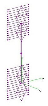
Vert-Stack FF6 + DoubleAngleRefl. (2 Jan 2016)UHF+Hi-VHF Vertically Stacked 2x FF6 (Free-Form 6-Bay Bowties) with Variable Double Angled Screen
Grid Reflector (VDAR) analyzed using 4nec2 after finding BEST Dimensions using nikiml's
Python Optimization Scripts. HVH (Holl_ands Vertical Harness) Interconnects two FF6's.
Screen Reflector (60" H x 36" W Unfolded) using 2x2-in Grid was assumed in fol. model
to remain within operating (and time) constraints. If 2x1-in Grid is used, F/B & F/R Ratios
would be much higher.
UHF Raw Gain = 18.2 to 20.6 to 20.3 dBi, F/B & F/R Ratio Min. = 13.0 dB and SWR (300-ohms) Under 2.3.
Hi-VHF Raw Gain = -4.1 to 13.0 to 12.4 dBi, F/B & F/R Min. = 17 dB Except Much Lower on Ch7+8
and SWR (300-ohms) is Excessive.
Note that UHF Elevation Beamwidth is only 5-3 degrees (and 10-deg for Hi-VHF), which requires
the user to KNOW the expected Angle of Arrival and mount the Antenna with sufficient LOOK UP ANGLE
(or in rare cases LOOK DOWN ANGLE). |
| 2118 Visits
35 Images
Shared Album | |
|
 | 3.
Vert-Stack FF4 + DoubleAngleRefl. (21 Apr 2014)UHF+Hi-VHF Vertical Stack 2 ea Free-Form 4-Bay (FF4) with Double Angle Reflector
(48" H x 36" W using 1x2-in Grid) were analyzed using 4nec2. FF4 dimensions
are same as found for Optimized version with Double Angle Reflector.
Many times Multipath results in signal strength varying with height in alternating Peaks and Nulls.
Zss = Vertical Stacking Separation between Antennas (Feedpoint-to-Feedpoint) was chosen
so that when Nulls form across the Bowties on one Antenna, hopefully Peaks will form across
the Bowties on the other.
Two versions are presented here, after using nikiml's Python Optimization Scripts to determine
"best" Stacking Distance (coincides with "best" Anti-Multipath) and Interconnection Parameters.
a) Two Equal Length 450-ohm Transmission Lines connect to a common Feedpoint (Balun):
Dimensions: Zss=59-in so Zmm=11-in (Reflector Metal-Metal) and TL Length=39-in each.
[Open Ladder type presumed. If "Windowed" Ladder with intermittent PLASTIC spaces,
then there can be High Loss when WET...which is NOT Included in these Calculations.]
UHF Raw Gain = 17.5 to 19.9 dBi, F/B & F/R Ratio Min = 15.2 dB & SWR (300-ohms) under 2.5.
Hi-VHF Raw Gain = 14.1 to 11.3 dBi, F/B & F/R Min=10.8 dB, although SWR (300-ohms) =
42 to 21 is EXCESSIVE, which may or may NOT be an issue in any particular situation.
I also ran Optimization runs for 300-ohm Twinlead, which resulted in nearly the SAME Gain,
F/B and F/R Ratio curves. However, SWR increased to as high as 4.1 at 698 MHz and mid-band.
So I do NOT recommend this alternative. FYI: Length of each Twinlead would be about 35-in,
where different lengths will move the double-humped SWR response curve to somewhat
different frequencies.
More info re "Windowed" and "Open Ladder" Balanced Transmission Lines (latter is weather resistant):
http://thewireman.com/antennap.html
http://www.arrg.us/pages/Loss-Calc.htm [Note Wet Loss for WM-551, 552, 553 & 554]
DIY PROJECT: http://www.qsl.net/co8tw/openline.htm
"Windowed" 450-ohm Twinlead is commonly used with Amateur Radio Antennas, but is
susceptible to significantly higher Loss in UHF Band when wet.
However, "Open Ladder" 440-ohm transmission lines are NOT affected by rain.
DIY Ladderline instructions are cited above, but Vertical Harness version would be
easier to construct and doesn't require any additional physical supports.
Note that although there is a very minor performance difference between 2xTL and VH versions,
presumably "better" 2xTL version does NOT take into account degradation from
Ladderlines in close proximity to antennas, so in reality they are probably about the SAME.
Hence Vertical Harness version is preferred:
#######################################################
b) The second was Optimized using a Vertical Harness between two FF4's, where distance
between Harness conductors and Total Length was searched to find "best" values:
Dimensions: VHw (FL Width)=1.0-in, VHp=3.25-in (Diagonally = 3.375-in), Feedlines=29.5-in,
Zss=60-in so Zmm=12-in (Reflector Metal-Metal).
UHF Raw Gain = 17.1 to 19.7 dBi, F/B & F/R Ratio Min = 14.3 dB and SWR (300-ohms) under 2.5.
Hi-VHF Raw Gain = 14.2 to 11.0 dBi, F/B & F/R Ratio Min = 10.0 dB although SWR (300-ohms)
= 73 to 19 is EXCESSIVE. |
| 4323 Visits
48 Images
Gallery Album | |
|
 | 4.
Vert-Stack FF4 SingleAngleRefl Sidelobes (31Jul2015)Vertical Stack FF4 (Free Form 4-Bay Bowtie) with Single Angle Reflector (providing Deep Sidelobe Nulls)
analyzed using 4nec2. HVH (Holl_ands Vertical Harness) dimensions were determined using nikiml's Python
Optimization Scripts. Each FF4 was assumed to be identical to the OPTIMUM non-stacked version found here:
http://imageevent.com/holl_ands/multibay/4bayrefl/uhffreeform4baysnglanglrefldeepsidelobes
UHF Raw Gain = 17.0 to 19.4 to 19.3 dBi, F/B & F/R Min. = 14.1 dB and SWR (300-ohms) under 2.4.
Hi-VHF Raw Gain = 12.0 to 11.5 dBi, F/B & F/R Ratio Min. = 12.7 dB and SWR (300-ohms) = 73 to 26 is Excessive.
SIDELOBE NULL RAW GAIN & ANGLE AWAY FROM MAX BEAM:
FREQ: 470 530 590 650 698 758 806 MHz
BEND:
2.0-in -3.1 -10.1 -11.6 -3.7 2.6 3.6 5.9 dBi
45-deg 40-deg 35-deg 35-deg 30-deg 25-deg 20-deg |
| 1854 Visits
21 Images
Gallery Album | |
|
 | 5.
Vert-Stack M4 (9.5x9) + DoubleAngleRefl. (9 Dec2013)UHF+Hi-VHF Vertically Stacked mclapp M4 (9.5x9-in) 4-Bay Bowties with Double Angled Reflectors
(40" H x 36" W using 1x2-in Grid) were analyzed using 4nec2, where Zmm = Metal-to-Metal
Separation between Reflectors.
A set of Parametric Sweeps for Zmm were conducted at 470, 584 and 698 MHz, which found
that there was only about +/- 0.2 dB Raw Gain difference as Zmm was varied.
SWR (300-ohms) was also Excellent, although rising slightly above 2.7 on 470 MHz at
Zmm=6.25 to 8.25-in, with only minor F/B & F/R Ratio differences.
Many times Multipath will result in signal strength varying with height in alternating Peaks
and Nulls. Zmm was chosen so that when Nulls form across the Bowties on one Antenna,
hopefully Peaks will form across the Bowties on the other. Hence they are NOT at equal spacing
across the entire Stack, as is found in many Narrow Band Antenna Arrays. In fact, per the
Charts, with equal Bowtie spacing (Zmm=7.25-in) Raw Gain, F/B & F/R Ratio would all be lower.
Three Versions with only slightly different performance are presented here.
The first two place equal strength SOURCEs at the Feedpoint of each 4-Bay to assess what is
achievable if fed from a "Perfect" RF Combiner. The third uses an Optimized Vertical Harness
to interconnect the 4-Bays, which can be expected to provide better performance in the "Real World":
a) RF Combiner Mod (with 0.5 to 1.5+ dB Combiner Loss NOT included):
"Best" Gain is a compromise, between Zmm= 2.25 to 4.25-in. Results are presented for
Zmm=2.75-in, for "Best" Anti-Multipath performance. Beamwidth narrows from 40 to 30-degrees.
UHF Raw Gain = 16.9 to 18.6 to 18.5 dBi, F/B & F/R Ratio = 19.4 to 16.1 dB and SWR (300-ohms) under 2.6.
Hi-VHF Raw Gain = 11.2 to 11.9 dBi, F/B & F/R Ratio = 13.6 to 18.8 dB and SWR (300-ohms) = 3.0 to 12.2.
############################################################
b) RF Combiner Mod (with 0.5 to 1.5+ dB Combiner Loss NOT included):
"Best" F/B & F/R Ratios (at the expense of small Gain reduction) is at Zmm=10.25 to 11.25-in.
Results are presented for Zmm=11.75-in, for "Best" Anti-Multipath performance.
UHF Raw Gain = 16.7 to 18.5 dBi, F/B & F/R Ratio = 20.7 to 16.3 dB and SWR (300-ohms) under 2.5.
Hi-VHF Raw Gain = 11.9 to 12.1 dBi, F/B & F/R Ratio = 14.8 to 20.3 dB and SWR (300-ohms) = 3.5 to 13.2.
Azimuthal Pattern Charts are nearly identical to those for Zmm = 2.75-in.
############################################################
c) Vertical Harness Interconnecting the Two 4-Bays. Results are presented for Zmm=2.75-in,
for "Best" Anti-Multipath performance. Beamwidth narrows from 40 to 30-degrees.
UHF Raw Gain = 16.8 to 18.2 dBi, F/B & F/R Ratio Min = 15.4 dB and SWR (300-ohms) under 2.4.
Hi-VHF Raw Gain = 11.0 to 11.7 dBi, F/B & F/R Ratio Min = 14.2 dB and SWR (300-ohms) = 1.6 to 36
is Excessive, except lowest channels.
Since lossy RF Combiner is not required, Vertical Harness version is preferred for UHF Band.
=====================================
UPDATE (9Feb2017): Conducted a "What-If" Investigation on third Alternative (c, with HVH)
to ascertain effect of extending BowLength for operation in New, New UHF Band [Ch14-36].
If SWR is kept no higher than 2.7 [Mis-Match = 1 dB], only a couple TENTHS of a dB Gain
increase are possible at BowLength = 10.5-in.
If SWR is allowed to be as high as 3.2 (Mis-Match = 1.4 dB), Gain Increase of 0.3 to 0.5 dB
is possible at BowLength = 11.25-db....hardly worth the effort.... |
| 3036 Visits
72 Images
Shared Album | |
|
 | 6.
Vert-Stack M4 (9.5x9) + NO Refl. + HHH (27 Dec 2013)UHF+Hi-VHF Vertically Stacked mclapp M4 (9.5x9-in) 4-Bay Bowties with NO Reflector
and Holl_ands Vertical Harness (HVH) was analyzed using 4nec2, with Zss = 42.75-in Vertical
Stacking Separation between Antennas (Feedpoint-to-Feedpoint). Dimensions are the same as found
for the Optimized version with the Double Angle Reflector.
UHF Raw Gain = 11.7 to 15.2 dBi, F/B & F/R = 0.3 to 0.6 dB and SWR (300-ohms) under 2.4.
Hi-VHF Raw Gain = 7.1 to 7.9 dBi, F/B & F/R = 0.7 to 0.6 dB and SWR (300-ohms) 5.5 to 2.5 to 6.9
Many times Multipath will result in signal strength varying with height in alternating Peaks
and Nulls. Zss was chosen so that when Nulls form across the Bowties on one Antenna,
hopefully Peaks will form across the Bowties on the other. Hence they are NOT at equal spacing |
| 2324 Visits
21 Images
Shared Album | |
|
 | 7.
UHF Vert-Stack CM4221 4-Bays - OPT (25 Nov 2013)UHF Vertically Stacked Channel Master (old) CM4221 analyzed using 4nec2.
Two versions are presented here, after using nikiml's Python Optimization Scripts to
determine "best" Stacking Distance and Interconnection Parameters.
In both versions, Antennas are separated by a Fixed amount (Metal-Metal Between
Screens = 4.05-inches) so that distance between Lower Bowtie on Upper Antenna and
Upper Bowtie on Upper Antenna is 1.5 times the individual Bowtie-Bowtie Separation.
This ANTI-MULTIPATH feature ensures that when Multipath conditions result in peaks and nulls
varying with height, at least one
Antenna will see mostly peaks when the other sees mostly nulls:
a) Two Equal Length 300-ohm Transmission Lines (aka "Twinlead") connect to a
common Feedpoint for connection to a Balun (NO RF Combiner). This provides highest
Raw Gain on higher channels, but is susceptible to increased loss when Twinlead gets wet.
UHF Raw Gain = 15.0 to 17.7 dBi, F/B & F/R Ratio Min = 11.9 dB & SWR (300-ohms) under 2.8.
[With 440 or 450-ohm Ladderline SWR improves to under 2.4 & NO Change to Raw Gain, F/B or F/R Ratio.]
Hi-VHF Raw Gain = 9.2 to 10.3 dBi REARWARD, with 4.9 to 7.7 dBi FORWARD and SWR (300-ohms)
is EXCESSIVE except on Ch11. MORE HI-VHF GAIN TO REAR THAN FORWARD.
Note that Hi-VHF Pattern can be turned around to the FRONT by using a much wider Reflector,
as was analyzed using M4 Super-4-Bay ("best" value T.B.D. for CM4221):
http://imageevent.com/holl_ands/multibay/4bayrefl/m49590gridrefl55
More info re "Windowed" and "Open" Balanced Transmission Lines (latter is weather resistant):
http://thewireman.com/antennap.html
http://www.arrg.us/pages/Loss-Calc.htm [Note Wet Loss for WM-551, 552, 553 & 554]
#######################################################
b) The second was Optimized using a Vertical Harness between the two CM4221's, where
the distance between the Harness conductors and the Total Length was searched to
find the "best" values.
UHF Raw Gain = 14.9 to 17.1 dBi, F/B & F/R Ratio Min = 11.2 dB and SWR (300-ohms) under 2.4.
Hi-VHF Raw Gain = 8.6 to 10.5 dBi REARWARD, F/B & F/R Ratio Min = 5 to 3 dB and SWR (300-ohms)
is EXCESSIVE except on Ch10. MORE HI-VHF GAIN TO REAR THAN FORWARD.
#######################################################
Two other Optimizations were conducted where the Stacking Distance was one of the variables,
but are not presented here since they had somewhat lower performance with Stacking Distance
nearly the SAME as for versions above, so were essentially the same versions. One of these
used Equal-Length Transmission Lines and the other a Vertical Harness similar to above. |
| 2873 Visits
45 Images
Shared Album | |
|
 | 8.
UHF Vertical Stacked A-D 91XG (17 Aug 2013)UHF Vertical Stacked, Antennas Direct 91XG 23-Element Corner-Yagis analyzed using 4nec2 with
various Separation Heights.
There is noticeable F/R Radio degradation and about 0.5 dB of Raw Gain Loss at 2-ft and 3-ft
Separation Height. F/R Ratio is only minimally degraded at 4-ft, with no degradation at 5 to 8-ft. |
| 4276 Visits
36 Images
Shared Album | |
|
 | 9.
UHF V-Stack 8-El FD-Yagi w. 2RR Ea - OPT (23 Jun 2013)UHF (16-Elements Total) Vertically Stacked 8-Element Folded Dipole Yagis
with 2 Reflector Rods each analyzed using 4nec2.
All dimensions were determined using nikiml's Optimization Python Scripts.
UHF Raw Gain = 11.3 to 14.5 dBi, F/B & F/R Ratio Minimum = 22.2 dB and SWR Under 3.0.
EDIT (27Jun2013): Updated Charts with improved results for Stacked 8-El FD-Yagis (w 2-Reflector Rods).
Newer version has 1+ dB improvement in Gain and F/R Ratio. Vertical Stacking Distance = 40-inches.
EDIT (11Nov2018): Added Performance Charts for 470, 584 and 698 MHz, varying Vertical
Stacking Distance from 10 to 110-inches [where VSD = 2 * Zyag]. Note that the "Sweet Spot"
for Raw Gain (+/- a few tenths of a dB) and SWR was for Vertical Stacking Distance between
30 and 40-in (Zyag from about 15 to 20-in). Across ALL Freqs, Optimizer determined VSD=40-in. |
| 2756 Visits
28 Images
Shared Album | |
|
 | 10.
Vert-Stack UHF Hourglass-Loop - NO Refl (14 Jun 2014)Vertically Stacked UHF Hourglass-Loops (NO Reflectors) analyzed using 4nec2.
All dimensions were determined using nikiml's Python Optimization Scripts.
An UHF Hourglass-Loop has a VERY WIDE Beamwidth of 80-deg at 470 MHz, decreasing to 70-deg at 698 MHz.
Vertically Stacked, remains 80-deg at 470 MHz, decreasing to 60-deg at 698 MHz (to within 10-deg resolution).
Two versions are presented here, the first presumes the use of an RF Combiner attached
to Antenna Feedpoints using Baluns & Equal Length Cables. The second avoids 0.5-1.5+ dB Loss
in RF Combiner by using an Optimized Vertical Interconnection Harness.
a) RF Combiner: Vertical Stacking (Center-Center), VD = 18-in provides Max Raw Gain per Optimizer.
UHF Raw Gain = 7.6 to 9.6 dBi and SWR (300-ohms) under 1.9.
=====================================
b) Holl_ands Vertical Harness: Vertical Stacking (Center-Center), VD = 24.75-in provides Max Raw Gain
per Optimizer. See 4nec2 File for all Dimensions, including Re-Optimized Hourglass-Loop sizes.
UHF Raw Gain FORWARD = 7.8 to 9.7 dBi, F/B & F/R Ratio has small (1.3 dB) increase at
high frequencies (just -0.1 dB at low frequencies), and SWR (300-ohms) under 2.1.
Dimensions of HVH wires were determined using nikiml's Python Optimization Scripts:
VS = 12.25-in = Vertical Stacking Distance (Center-To-Center).
VS/2 = 6.125-in, Length of Harness wires from Feedpoint to Center of each Hourglass-Loop.
Diagonal = 3.25-in, Length from Harness Wires to each Hourglass-Loop Feedpoint.
Hw = 0.80-in (may round to 0.75-in),
Xh = -3.25-in = Harness X-Axis Separation from Hourglass-Loops.
TOTAL HARNESS WIRE LENGTH (2 required) = 19.75-in = 2x6.125+2x3.25+2x0.5 (for eyelets) |
| 1934 Visits
42 Images
Shared Album | |
|
 | 11.
V-Stack UHF Hourglass-Loop + 15RR (11 Jul 2014)V-Stack UHF Hourglass-Loop + 15RR
UHF Vertically Stacked Hourglass-Loops with 15 Reflector Rods analyzed using 4nec2
where nikiml's Python Optimization Scripts were used to Optimize dimensions of the
HVH (Hollands Vertical Harness) and Separation between Hourglass-Loops.
UHF Raw Gain = 12.6 to 13.7 dBi, F/B & F/R Ratio Min = 18.3 dB and SWR (300-ohms) under 2.8.
Beamwidth = 60-degrees was CONSTANT vs Frequency.
Dimensions of HVH wires were determined using nikiml's Python Optimization Scripts:
VS = VS=17.5-in = Vertical Stacking Distance (Center-To-Center).
VS/2 = 8.75-in, Length of Harness wires from Feedpoint to Center of each Hourglass-Loop.
Diagonal = 1.0-in, Length from Harness Wires to each Hourglass-Loop Feedpoint.
Hw = 1.125-in (may round to 1.5-in),
Xh = -0.5-in = Harness X-Axis Separation from Hourglass-Loops.
TOTAL HARNESS WIRE LENGTH (2 required) = 20.5-in = 2x8.75+2x1.0+2x0.5 (for eyelets) |
| 4821 Visits
18 Images
Gallery Album | |
|
 | 12.
V-Stack UHF Quad-Trap-Loop - 15RR (30 Dec 2014)Vertical Stack of UHF Quad-Trapezoid-Loops with 15 Reflector Rods analyzed using 4nec2
after determining Optimum Dimensions for the Holl_ands Vertical Harness using nikiml's
Python Optimization Scripts with NO change to individual Optimized QTL Dimensions.
a) UHF Quad-Trap-Loop with 15 Reflector Rods (UHF ONLY Optimization):
UHF Raw Gain = 13.1 dBi, F/B & F/R Ratio Min = 18.0 dB and SWR (300-ohms) under 2.9.
Hi-VHF Raw Gain = 7.5 to 8.6 to 6.0 dBi HIGHER TO REAR, F/B & F/R Ratio = 3.3 to 13.0 to 9.3 dB
and SWR (300-ohms) = 520 to 1.6 to 5.1 is EXCESSIVE over MOST of the Hi-VHF Band.
Hi-VHF Raw Gain = 4.3 to -6.8 to -3.3 dBi FORWARD [WIDER RR's should help.]
b) UHF Quad-Trap-Loop with 15 Reflector Rods (Hi-VHF & UHF Optimization):
T.B.D. |
| 1721 Visits
24 Images
Gallery Album | |
| |