 | 1.
FM Flat-Swept SBGH H-POL OMNI-PLUS (5 Jul 2016)FM Flat-Swept SBGH (Single Bay Grey Hoverman) Horizontally-Polarized OMNI-PLUS Antenna analyzed using
4nec2 after determining BEST Dimensions using nikiml's Python Optimization Scripts. Just one of my ANTZZ (see Cartoon).
Even after imposing a Height CONSTRAINT, it is still 194.6-inches (16.2-ft) Tall, presuming 1/4-in Copper (maybe 1/2-in or larger):
Min Gain = 4.5 dBi, Max Gain = 7.5 dBi, SWR (300-ohms) under 2.3.
This H-Pol. Antenna provides OMNI+PLUS Azimuthal Pattern (Greater than 0 dBd = 2.15 dBi Gain in every direction),
with a MINIMUM Gain of 4.5 dBi or MORE on ALL Azimuths.
Without a Height CONSTRAINT, it was TWICE as Tall with only a few tenths of a dB Gain Improvement
and Excessive SWR...hence it is not presented here. |
| 2518 Visits
18 Items
Shared Album | |
|
 | 2.
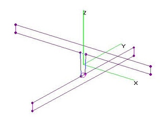
FM TRIAD 4xRectangular-Loops H-OMNI-PLUS (4Oct2018)FM TRIAD of 4xRectangular-Loops Array, Horizontal OMNI-PLUS Array analyzed using 4nec2.
FM Raw Gain = 3.3 to 4.4 dBi [across all Angles & Freqs] and SWR (300-ohms) is Under 3.0,
which is roughly 1.2 to 2.2 dB higher than a 0 dbd = 2.2 dBi Omni....hence I call it an "OMNI-PLUS".
DIMENSIONS (all in inches, from 4nec2 File):
Z-Coord Height of Each Loop [Loop Height]: H=25 [hench Total = 100-in]
Y-Coord Loop Width: W=35
Element to Center Array Radius: Ra=20.75
Feedpoint Gap at Middle of Dipoles: [Adjusts Impedance of Feedlines]: Gap=10
Z-Coord Length of Common Feedpoint: [Adjusts Impedance of Feedlines]: Zg=9
Z-Coord Offset between Source and Dipoles: [Adjusts Length of Feedlines]: Zo=0 [CONSTRAINT: Not Needed]
Element Diameter: dia=0.1875 [3/8-in O.D.]
Note that Balun Wires would form the 9-in Length of the Vertical Common Feedpoint Wire at the Center. |
| 1602 Visits
17 Items
Shared Album | |
|
 | 3.
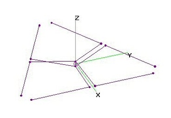
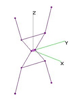
FM Goalkeeper Quad-Trap+Spurs Quasi-OMNI (22 Jul 2014)FM Goalkeeper, a Quasi-Omni [accidental] variation of the Quad-Trapezoid+Spurs
with Horizontal Polarization was analyzed using 4nec2.
FM Band Raw Gain = 2.4 to 3.1 to 2.7 dBi (Forward & Rear) and SWR (300-ohms) under 2.7 (Excellent).
Beamwidth = 100-110 degrees.
Provides Bi-Directional Pattern firmly aligned along the X-Axis with wide Beamwidth
and NULLs to the sides. Although Horizontally Polarized, it also provides both
Right-Hand and Left-Hand Circular Polarization, but with only 1 dB LHCP suppression. |
| 4775 Visits
12 Items
Shared Album | |
|
 | 4.
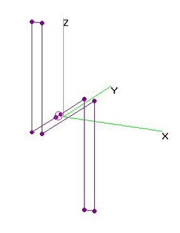
FM TRIAD Array of Dipoles H-OMNI (4Oct2018)FM TRIAD Array of Dipoles, Horizontal-OMNI analyzed using 4nec2, based on design by L. B. Cebik, W4RNL,
with 4nec2 File prepared by Carol F. Milazzo, KP4MD, see http://www.qsl.net/kp4md/omnihoriz.htm
FM Raw Gain = 0.3 to 1.6 dBi [across all Angles & Freqs] and SWR (300-ohms) is Under 2.6,
which is roughly 1.9 to 0.6 dB LOWER than a 0 dbd = 2.2 dBi Omni.
Note that 75:300-Ohm Balun Wires form the Simulated Vertical Source Wire, which is CRITICAL
to Performance and needs to be 6-in Long. Three Feedlines run from there to each Dipole's
mid-point Gap = 0.5-in, whose dimension is also CRITICAL for Performance. |
| 1467 Visits
16 Items
Shared Album | |
|
 | 5.
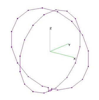
FM Double-Hoop H-POL OMNI (17 Dec 2011)FM Double-Hoop Omni antenna analyzed using 4nec2.
Similar to Antennas Direct FM-360-HD, Antiference FM1080, Dipol A0210/A0220, Fracarro "FM Omni", Televes 1201,
Triax "FM Omni" & Stellar Labs 30-2435.
This antenna responds to Horizontal (ONLY) Polarization.
Horizontally Polarized Raw Gain is not quite Omni-Directional, ranging from -2.1 to +1.3 dBi, depending on angle & frequency.
SWR (300-ohms) is 6.2-11.5 |
| 7473 Visits
15 Items
Shared Album | |
|
 | 6.
FM Double-Hoop + Vertical-Dipole Outside (17 Dec 2011)FM Double-Hoop plus Vertical Dipole Outside analyzed using 4nec2.
This antenna responds to both Horizontal and Vertical Polarization, although they are only have equal Raw Gain at about 97 MHz.
Below 97 MHz, Vertical Gain is reduced by more than 10 dB and above 97 MHz Horizontal Gain is reduced by more than 10 dB.
However, Total Gain (Vert. + Horiz.) remained between -1.9 and +2.1 dBi across all angles and frequencies.
SWR (75-ohms) was under 5. SWR (300-ohms) was excessive on the lowest frequencies.
Although Raw Gain varies quite a bit, the Omni-Directional azimuthal coverage remains very consistent across all angles.
However, users may be unhappy with performance if a station is only transmitting one Polarity. |
| 4713 Visits
15 Items
Shared Album | |
|
 | 7.
FM Double-Hoop + Vertical-FD-Outside (23 Dec 2011)FM Double-Hoop plus Vertical-Folded-Dipole-Outside analyzed using 4nec2.
This antenna responds to Horizontal and Vertical Polarization, with a Horizontal Gain of -3.9 to +1.2 dBi.
Vertical Whip max was -1.4 dBi with a -22 dBi Gain hole on lower freqs for Vertically Polarized signals.
Total Gain (Vert. + Horiz.) remained between -2.3 and -1.4 dBi across all angles and frequencies.
However, users may be unhappy with performance if a station is only transmitting Vertical Polarity.
SWR (300-ohms) was 6.4-6.8. |
| 6386 Visits
15 Items
Shared Album | |
|
 | 8.
FM Double-Hoop + Vert. Dipole In Center (21 Dec 2011)FM Double-Hoop plus Vertical Dipole Omni (IN CENTER OF HOOP) analyzed using 4nec2.
This antenna responds to both Horizontal and Vertical Polarization, although they are only have equal Raw Gain at about 97 MHz.
Below 97 MHz, Vertical Gain is reduced by up to 9 dB and above 97 MHz Horizontal Gain is reduced by up to 5 dB.
However, Total Gain (Vert. + Horiz.) remained between -1.2 and +2.3 dBi across all angles and frequencies.
SWR (300-ohms) was under 6.2
Although Raw Gain varies quite a bit, the Omni-Directional azimuthal coverage remains very consistent across all angles.
However, users may be unhappy with performance if a station is only transmitting one Polarity. |
| 4491 Visits
15 Items
Shared Album | |
|
 | 9.
FM Double-Hoop + Vertical-FD-In-Center (23 Dec 2011)FM Double-Hoop + Vertical-Folded-Dipole In Center analyzed using 4nec2.
This antenna responds to Horizontal and Vertical Polarization, with a Horizontal Gain of -5.2 to +0.8 dBi.
Vertical Whip max was +1.2 dBi with a -10 dBi Gain hole on lower freqs for Vertically Polarized signals.
Total Gain (Vert. + Horiz.) remained between -1.8 and +2.3 dBi across all angles and frequencies.
However, users may be unhappy with performance if a station is only transmitting Vertical Polarity.
SWR (300-ohms) was 2.2-7.2. |
| 4803 Visits
18 Items
Shared Album | |
|
 | 10.
FM Double-Hoop + Vertical Whip Outside (17 Dec 2011)FM Double-Hoop plus Vertical Whip Outside analyzed using 4nec2. Similar to Dipol A0221 Antenna:
http://www.dipolnet.com/estore-antennas-fm,4346.htm
This antenna responds to Horizontal and Vertical Polarization, but Raw Gain is not very consistent on all angles.
Vertical Whip has a Gain hole on lower freqs for Vertically Polarized signals.
Total Gain (Vert. + Horiz.) remained between -3.2 and +1.9 dBi across all angles and frequencies.
However, users may be unhappy with performance if a station is only transmitting Vertical Polarity.
SWR (300-ohms) was 5.1-7.1. |
| 4673 Visits
15 Items
Shared Album | |
|
 | 11.
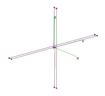
FM Vertical Folded Dipole VPOL TRUE-OMNI (17 Dec 2011)FM Vertical Folded Dipole TRUE-OMNI-Directional Antenna with Vertical Polarization
analyzed using 4nec2.
Details on building a Horizontal Folded Dipoles (rotated 90-deg) can be found here:
http://imageevent.com/holl_ands/loops/folded
http://imageevent.com/holl_ands/loops/vhffoldeddipole
Note that increasing Separation between the Elements requires reduced Length to compensate.
Presumes a HICT (Half-Inch Copper Tubing, Actual O.D. = 0.569-in) and 4-in Separation between
the Folded Elements, Optimum Overall Length = 55.0-in.
Vertically Polarized Raw Gain is not quite Omni-Directional, ranging from +1.7 to +2.6 dBi,
depending on angle & frequency.
SWR (300-ohms) is under 2.0 across the entire FM Band. |
| 8963 Visits
15 Items
Shared Album | |
|
 | 12.
FM Vertical Stick Dipole V-POL TRUE-OMNI (21 Jan 2015)FM Vertical Stick Dipole TRUE-OMNI with Vertical Polarization analyzed using 4nec2 after
adjusting Length for "best fit" of SWR across the FM Band.
For HICT (Half-Inch Copper Tubing, actually O.D. = 0.569-in), Optimum Overall Length = 57.4-in.
Since Antenna Pattern is a Low-Gain Omni, 75-ohm Coax can be connected DIRECTLY to Center Feedpoint,
eliminating any Loss in a 1:1 Balun, with minimal Common Mode Current impact on the Antenna Pattern
(as expected in High-Gain Yagi's).
Response to RHCP (Right Hand Circular Polarization) is the same as for LHCP (Left Hand Circular Polarization)
signals, so there is no suppression of Multipath Reflections. [Most Reflections reverse Handedness.] |
| 6505 Visits
18 Items
Shared Album | |
|
 | 13.
FM + VHF Discone V-POL TRUE-OMNI (26 Aug 2012)FM + VHF 8-Spokes Vertically Polarized Discone Antenna analyzed using 4nec2.
I determined dimensions mostly via trial and error, resulting in barely acceptable (3:1) SWR on
the lowest frequency (88 MHz) and reduced Gain (0 dBi) on the highest frequency (216 MHz).
Gain=1.4 dBi in FM Band. [Somewhat larger antenna JUST for FM Band adds 0.2-0.3 dBi.]
Presumed use of AWG10 and 60-degree Complimentary Cone Angle measured from the X-Y Plane.
[Some references measure Cone Angle to the Z-Axis.]
Cone Whisker Length=36-in, Disc Radius=20-in, Feedpoint Gap=2.0-in, Inner Circle Radius=1-in.
Polarization is almost completely Vertical.
Elevation Gain charts reveal that Gain in FM Band is directed at Horizon (Elev=0-deg).
However, in Hi-VHF Band, Gain is significantly below the Horizon...hence the depicted antenna
SHOULD be mounted UPSIDE-DOWN from shown.
Ditto for commonly encountered off-the-shelf VHF Discone Antennas. |
| 6535 Visits
19 Items
Shared Album | |
|
 | 14.
FM Monopole Whip over Groundplane OMNI (21 Dec 2011)FM Monopole Whip over a 38-in x 24-in Groundplane anallyzed using 4nec2. Length=32-in optimized for best SWR.
This antenna responds to Vertically Polarized signals, with minimal response to Horizontal Polarization.
Vert. Pol. Gain only varied from 1.54 to 1.62 dBi for all angles and frequencies, an Excellent Omni characteristic.
SWR (75-ohms) is 3.0-4.5 (just slightly worse than Optimum 71-ohms "best fit"). |
| 6716 Visits
17 Items
Shared Album | |
|
 | 15.
FM Turnstile QuasiOMNI Antennacraft FMSS (22 Dec 2011)Antennacraft FMSS FM Turnstile (two Folded Dipoles at 90-degrees to each other) analyzed using 4nec2.
[Similar to Wade CFM-FM, Wade OFM-1 and Winegard HD-6010, except non-Folded is 75-ohm output.]
Per FMSS Specs, Folded Dipole Elements = 55-in long with overall structure Height = 8-in.
Separation between Elements appears to be about 2-in, leaving about 4-in between the Crossed FD's.
Per FMSS Manual, Feedline is 9-in long and appears to be 450-ohms open ladder twinlead,
although modeling with 300-ohm twinlead revealed minimal differences, assuming it was the
same ELECTRICAL length (shorten by velocity factor).
Antenna Pattern maximums are on two diagonals, 300-deg for High Freqs and 335-deg for Low Freqs.
There are significant Gain Holes on the opposite Diagonals (40-60 & 220-240 degrees).
Across all angles and frequencies, Raw Gain ranges from -14 to +1.3 dB (Horizontally Polarized).
SWR (300-ohms) was 2.9, dropping to 1.5 at high frequencies.
FYI: FMSS Folded Dipole lengths are not quite optimum for Min SWR. Longer, 62.5-in FD Elements
minimized SWR, which was under 1.9, but decreased Raw Gain by a few tenths of a dB. |
| 8657 Visits
17 Items
Shared Album | |
|
 | 16.
FM Turnstile Quasi-Omni - Alternate (21 Dec 2011)FM Turnstile (two Folded Dipoles at 90-degrees to each other) analyzed using 4nec2.
Separation between Folded Dipole Elements = 3-in, overall Height = 14-in.
Folded Dipole lengths were tweaked to minimize SWR, resulting in two different lengths:
51.5-in for 75-ohms and 62-in for 300-ohms, presuming 3-in FD Element Separation. Both are shown below.
Antenna Pattern maximum is on two diagonals, 300-deg for High Freqs and 335-deg for Low Freqs.
There are significant Gain Holes on the opposite Diagonals (40-60 & 220-240 degrees).
Across all angles and frequencies, Raw Gain ranges from -13 to +1.4 dB (Horizontally Polarized).
SWR (75-ohms) is 1.8-3.2 with minimum mid-band, however SWR (300-ohms) is 3.5 dropping to 1.6, so either may be used. |
| 5410 Visits
17 Items
Shared Album | |
|
 | 17.
FM Turnstile - A-C FMSS Rotated (22 Apr 2013)Antennacraft FMSS FM Turnstile, ROTATED to receive both Horizontally and Vertically Polarized signals
ALSO is a fairly good RHCP (Right Hand Circularly Polarized) antenna when signal direction along X-Axis.
Carefully check interconnections to ensure this happens in "forward" rather than "reverse" direction.
Vertical Polarization is very consistent, but Horizontal Polarization exhibits the usual Bi-Directional Pattern.
Vertical Gain remained between -1.6 and +0.7 dBi across all angles and frequencies.
However, Horizontal Gain exhibited the usual Bi-Directional pattern, with Gain in Forward Direction
between -3.1 and +0.1 dBi and Gain Nulls to either side.
When receiving a RHCP signal, Total Gain (Vert. + Horiz.) remained between -1.6 and +2.3 dBi across all angles
and frequencies, with a moderate RHCP/LHCP Cross-Polarization Ratio between 7 dB (108 MHz)and 10.4 dB (98 MHz). |
| 4831 Visits
14 Items
Shared Album | |
|
 | 18.
FM ESS Curves - Fracarro & Dipol (27 Dec 2011)FM ESS Curve Quasi-Omni Antennas analyzed using 4nec2. Although Vertical Polarization pattern was
mostly Omni-directional, the Horizontal pattern was Bi-Directional, with deep nulls to the sides.
Fracarro ANT1200A specifications list Height=38in (96-cm) and Width=30-in (77-cm) with 75-ohm Type "F" output
(e.g. 300:75-ohms Balun). Fracarro claims Max Gain=2.1 dB?, F/B Ratio="OMNI", -3 dB Beamwidth=360-deg
and Return Loss=-16 dB (SWR Under 1.38): http://www.fracarro.es/download/prodottitvsat/Aerials/FM_SERIES.pdf
A 4nec2 model was constructed, assuming two variable length (="Middle") wires at the mid-point with Z=0 (along Y-Axis).
At either end of the Middle wires are quarter-circle arcs with Radius-Of-Curvature=0.5*(Width-Middle), to which are attached
straight up-and-down wires extending to +/- Height/2.
Actual dimensions may be slightly different, e.g. Separation between ESS's may be (inconsequential) 2.5-in vice 2.0-in.
The "optimum" length for "Middle" (7.6-in) was found by running a nikiml optimization script on the 4nec2 file (mostly Min SWR).
Fracarro 4nec2 Results: For Vertically Polarized signals, the Azimuthal Pattern was close to Omni-directional,
varying from -4.4 to -1.4 dBi across all angles and frequencies. However, for Horizontally Polarized signals,
the pattern was Bi-Directional, with deep nulls to the sides, varying from -34 to +0.1 dBi.
Across all angles and frequencies, Total Raw Gain ranges from -4.4 to +2.3 dB (Horizontal + Vertical).
SWR was excellent, between 1.3 in middle and 2.7 at band edges.
=============================================================================
Dipol A0222/A0223 specifications are very sparse. Gain curve starts at -3 dBi, rising to -1 at mid-high frequencies.
Impedance is 300-ohm (no Balun) and they (erroneous) indicate that it has Horiz. and Vert. (wrong) polarization.
Size is indeterminate: http://www.dipolnet.com/estore-antennas-fm,4346.htm
Blowing up and comparing the photo of the Dipol A0222/A223 to the Fracarro ANT1200A reveals that they are
very similar, except for being mirror images about the Z-Axis. After reversing the sign of all Y-Axis coordinates
in the Fracarro 4nec2 file, it was compared to the Dipol photo, which appears to be slightly shorter, wider and smaller
Separation between the two ESS's compared to the Fracarro. 4nec2 file was adjusted to best match Dipol's photo:
Height=37in, Width=33in, Middle=6in & Separation=2-in.
Dipol 4nec2 Results: For Vertically Polarized signals, the Azimuthal Pattern was close to Omni-directional,
varying from -5.1 to -1.9 dBi across all angles and frequencies. However, for Horizontally Polarized signals,
the pattern was Bi-Directional, with deep nulls to the sides, varying from -36 to +0.4 dBi.
Across all angles and frequencies, Total Raw Gain ranges from -5.1 to +2.4 dB (Horizontal + Vertical).
SWR was excellent, between 1.3 in middle and 2.5 at band edges. |
| 7498 Visits
31 Items
Shared Album | |
|
 | 19.
FM ZigZag - Triax FM Zigma (30 Dec 2011)FM ZigZag Antenna, similar to Triax FM Zigma, analyzed using 4nec2.
Triax FM Zigma Specs:
Gain = -1.0 dBi, F/B Ratio = 0 dB, Beamwidth = +/- 45-deg (Horizontal Polarization) and +/- 180-deg (Vertical Pol.).
Erroneously] "Length" [Width!!!] = 550-mm and "Width" [Height!!!] = 1140-mm:
http://www.triax.co.uk/upload/gb_-_triax_main_catalogue_2009.pdf
Triax FM Zigma Dimensions: Height = 44.88-in, Width = 21.65-in, Separation = 2.0-in.
Separation was a Guesstimate, based on Triax's picture. If it were 3.0-in, SWR is under 3.5 with negligible change in Gain.
Triax FM Zigma 4nec2 Results: For Vertically Polarized signals, the Azimuthal Pattern was close to Omni-directional,
varying from -1.5 to -0.7 dBi across all angles and frequencies. However, for Horizontally Polarized signals,
the pattern was Bi-Directional, with deep nulls to the sides (like a Folded Dipole), varying from -39 to -1.7 dBi.
Across all angles and frequencies, Total Raw Gain ranges from -1.5 to +2.4 dB (Horizontal + Vertical).
SWR (300-ohms) is under 3.7.
==============================================================================
A parameter search was conducted to find the dimensions for which the Vert. Pol. Gain was roughly equal to
Horiz. Pol. Gain and hence provided optimal response to Circularly Polarized signals. Results are below.
FM ZigZag Cir. Pol. Dimensions: Height = 39-in, Width = 22-in, Separation = 2.0-in.
Note that Cir. Pol. condition is only found in the Forward and Reverse directions due to Horiz. Pol. nulls on sides.
FM ZigZag 4nec2 Results: For Vertically Polarized signals, the Azimuthal Pattern was close to Omni-directional,
varying from -2.5 to -0.4 dBi across all angles and frequencies. However, for Horizontally Polarized signals,
the pattern was Bi-Directional, with deep nulls to the sides (like a Folded Dipole), varying from -37 to -1.1 dBi.
Across all angles and frequencies, Total Raw Gain ranges from -2.5 to +2.3 dB (Horizontal + Vertical).
SWR (300-ohms) is under 3.7.
FYI: There were many nikiml python script solutions with SWR under 3.0, but NONE came close to Cir. Pol. condition. |
| 5174 Visits
26 Items
Shared Album | |
|
 | 20.
FM Right Circular Folded Dipole Pair (2 Jan2012)FM Right Circular Folded Dipole Pair analyzed using 4nec2. The Folded Dipole Pair was based on
K6STI's circdip3.nec Dipole Pair file found in C:/4nec2/models/VHFsimple.
K6STI's original file was modified to add the Elements completing two Crossed Folded Dipoles and was
Resized for the FM Band, with final adjustment so that the Circular Polarization was in the FORWARD
direction at 98 MHz (and REVERSE direction at 97 MHz).
EDIT (16Jan2012): Added Circular Polarization Azimuthal Charts. It's Right Hand Circular FORWARD and
Left Hand Circular to REVERSE, so carefully inspect antenna to verify direction. LHCP Suppression is reduced on low freqs. |
| 6382 Visits
21 Items
Shared Album | |
|
 | 21.
FM Cycloid Dipole - Circular Polarized (29 Dec 2011)FM Cycloid Dipole Omni Antenna with Circular Polarization analyzed using 4nec2.
For more info re Cycloid, see: http://www.wa7x.com/cycloid_info.html
Although Raw Gain Vertical, Horizontal and TOTAL (Vertical + Horizontal) Polarization was fairly constant
across all angles and frequencies, the Impedance varied considerably. It was 9.2+127j ohms at 87 MHz,
rising to 37+410j ohms at 108 MHz, making it very difficult to design a wide-band matching network.
Best SWR was about 30:1 with 186-ohm load. Although Analog FM is tolerant of high SWR, Digital FM may not be.
Suppression of Left Hand Circular Polarization (LHCP) is very good across entire FM Band.
Intended for broadcast applications, this (and similar) antennas can be matched to 50-ohms (or 300-ohms)
for a NARROW RANGE OF FREQUENCIES by using a matching network (hit "F10" key, L/Pi/T Matching in 4nec2).
Matched SWR Chart (at bottom) was the SAME, with ANY of the L, Pi or T Filters - Low or High Pass. |
| 10460 Visits
23 Items
Shared Album | |
|
 | 22.
490 MHz Flat-Swept SBGH H-POL OMNI-PLUS (21 Feb 2016)490-MHz Flat-Swept SBGH (Single-Bay Grey-Hoverman), Horizontally-Polarized OMNI-Directional
Antenna was analyzed using 4nec2 after Optimization by nikiml's Python Scripts.
Min Gain = 7.2 dBi, Max Gain = 9.3 dBi. This H-Pol. Antenna provides OMNI+PLUS
Azimuthal Pattern (Greater than 0 dBd = 2.15 dBi Gain in every direction), with a MINIMUM Gain
of 7.2 dBi or MORE on ALL Azimuths. It is well matched to a Characteristic Impedance of 200-ohms,
requiring the use of a 4:1 Balun (usually Coax type) to match 50-ohm Load with an SWR
of less than 1.5:1, which is well within a typical Transmitter Limit of 2:1.
Although specifically designed for an 8-MHz bandwidth DVB-T Ch23 Micro-Transmitter, the
dimensions can be Rescaled to any desired Center Frequency by Fraction F = New Freq / 490 MHz
[Smaller for Higher Freqs].
Adequate signal levels very close to Transmit Tower were also analyzed, since higher Gain Antennas
may have an Elevation Gain Pattern that is TOO narrow with only minimal signal level being
directed DOWN to nearby homes. The Elevation Pattern only has a few degrees where the
Gain drops below -20 dBi at about 36-deg Down Look Angle. This should NOT be much of a
close-in Coverage problem (if at all) with this Antena, bearing in mind that signal levels are
20 dB HIGHER at 0.1 km as they are at 1 km, as the Path Loss decreases ever closer to the Tower.
EDIT (23Mar2016): Replaced SIDE VIEW with FLAT VIEW Dimensioned Drawing for Each Zig-Zig.
EDIT (13Apr2016): Updated Spread Sheet, adding Double (Crossed) Diamond (Quad) Array
performance and SNR Margin (et. al.) Calculation for Dipole Triad Array vs Flat-Swept SBGH.
EDIT (14Apr2016): Updated Spread Sheet, adding estimate for Analog PAL Required SNR. |
| 3397 Visits
26 Items
Shared Album | |
|
 | 23.
490 MHz Flat-Swept SBGH OMNI + TOP-HAT (27 Feb 2016)490-MHz Flat-Swept SBGH (Single-Bay Grey-Hoverman), Horizontally-Polarized OMNI-Directional Antenna
with 36-in Radius "Top-Hat" [to improve Look-Down Angle, i.e. Negative Elevation Pattern Gain]
was analyzed using 4nec2.
Min Gain = 7.1 dBi, Max Gain = 9.0 dBi. Although this H-Pol. Antenna doesn't provide TRUE OMNI
Azimuthal Pattern (equal Gain every direction), it DOES provide a MINIMUM Gain of 7.1 dBi or MORE
on ALL Azimuths. It is well matched to a Characteristic Impedance of 200-ohms, requiring
the use of a 4:1 Balun (usually Coax type) to match 50-ohm Load with an SWR of less than 1.5:1,
which is well within a typical Transmitter Limit of 2:1.
Although specifically designed for an 8-MHz bandwidth DVB-T Ch23 Micro-Transmitter, the
dimensions can be Rescaled to any desired Center Frequency by Fraction F = New Freq / 490 MHz
[Smaller for Higher Freqs]. |
| 3416 Visits
14 Items
Shared Album | |
|
 | 24.
490 MHz 3-Dipole TRIAD Array H-POL OMNI (15 Feb 2016)490-MHz 3-Dipole Triangle Array, Horizontally-Polarized OMNI-Directional Antenna analyzed
using 4nec2. This is one of the very few H-Pol. Antennas that are provide a TRUE OMNI Azimuthal Pattern,
with an Outstanding Gain variability of only +/- 0.1 dB vs Angle and even less than that vs Frequency.
Gmin = 1.2 dBi, Gmax = 1.4 dBi. Characteristic Impedance = 200-ohms. Provides better Gain
and SWR with 200-ohm Balun (requiring use of a 4:1 Balun (usually Coax type) than 50-ohm
(with 1:1 Coax Balun)....whose SWR of about 1.7:1 was acceptable, but uncomfortably close
to a typical Transmitter Limit of 2:1, leaving little room for other SWR detriments.
Although specifically designed for an 8-MHz bandwidth DVB-T Ch23 Very Low Power Transmitter,
the dimensions can be Rescaled to any desired Center Frequency by Fraction F = New Freq / 490 MHz
[Smaller for Higher Freqs].
Although NOT a problem with THIS OMNI Antenna, adequate signal levels very close to the Transmit Tower
is of interest, since higher Gain Antennas may have an Elevation Gain Pattern that is TOO narrow with
only minimal signal level being directed DOWN to nearby homes....bearing in mind that signal levels are
20 dB HIGHER at 0.1 km as they are at 1 km, as the Path Loss decreases ever closer to the Tower. |
| 3350 Visits
15 Items
Shared Album | |
|
 | 25.
490 MHz Crossed-Dipoles + One TL - OMNI (3 May 2016)490 MHz Crossed Dipoles (Interconnected with One Feedline), analyzed using 4nec2 after
Dimensions determined using nikiml's Python Optimization Scripts.
Azimuthal Pattern for Horizontal Polarization is a TRUE OMNI with about -1 dBi Gain (+/- 1 dB)
and very low SWR (Under 1.03). Horizontal Gain was only slightly reduced
for moderate to large negative Elevation Angles, hence Look Down Angle coverage is Very Good.
Azimuthal Pattern for Right Hand Circular Polarization (RHCP) was not quite a True Omni
with about -3 dbc Gain (+/- 1.5 dB) and very low SWR (Under 1.03). Note that as shown,
RHCP covers LOWER Hemisphere. To change so RHCP covers UPPER Hemisphere,
reverse Feedlines to Upper Dipole.
For about 3 dB more Gain, two Vertically Stacked Crossed Dipoles could be used.
And for about ANOTHER 3 dB more Gain a Turnstile with FOUR Crossed Dipoles could be used.
SUMMARY OF DIMENSIONS: [From 4nec2 File]
Relem=5 ' Element Radius (millimeters)
VF1=1.00 ' Feedline Velocity Factor [OPEN LADDER]
F=0.996 ' RESCALE FACTOR [487 TO 490 MHZ]
HL=F*125=124.5 ' Half-Length of Dipoles (millimeters) (Max Y-axis Coordinates)
Zdd=20 ' Z-Axis Dipole-to-Dipoles Separation
L1=F*28.5=28.4 ' Feedine PHYSICAL Length (IN MM) Between Dipoles
FL1=VF1*L1/1000=0.0284 ' Feedline Electrical Length (IN METERS) between Dipoles
Zc1=342 ' Characteristic Impedance (ohms) of Feedline Between Dipoles
Resultant Optimization favored the lowest SWR, rather than Uniform Gain in all directions.
Hence I applied a small RESCALE FACTOR to recenter "Best" performance from 487 to 490 MHz.
Due to short length (28.4-mm), construction of the Interconnecting Feedline is NOT
critical, with 0.75-in separation between AWG10 or AWG12 or AWG14 working equally well. |
| 2459 Visits
39 Items
Shared Album | |
|
 | 26.
490 MHz Crossed-Dipoles, 2 Unequal TLs (3 May 2016)490 MHz Vertically Stacked Crossed Dipoles (Interconnected with two Unequal Feedlines),
analyzed using 4nec2 after Dimensions determined using nikiml's Python Optimization Scripts.
It was found to be a TRUE OMNI, with roughly SAME Gain on all Azimuths, but SWR was poor
and would need an additional Matching Network or Quarter-Wavelength Impedance Transformer.
Horizontally Polarized Raw Gain = -1.5 dBi (+/- 1 dB) and SWR (50-ohms) = 2.0, which is
right at limit for tripping the self-protect circuitry in some Transmitters, with no margin
left to accommodate likely SWR degradations in the Feedline, construction inaccuracies
and Proximity to Nearby Objects.
SUMMARY OF DIMENSIONS: [From 4nec2 File]
Relem=5 ' Element Radius
Gap=20 ' FEEDPOINT GAP (SIMULATED BALUN CONNECTION)
VF1=0.66 ' Velocity Factor, Feedline to Top Dipole
VF2=0.66 ' Velocity Factor, Feedline to Top Dipole
' Half-Length of Dipoles (millimeters) (Max Y-axis Coordinates):
HL=152
' Distance Dipoles are Above and Below Z=0 Axis (millimeters):
Zd1=150
Zd2=250
' Feedine PHYSICAL Length (IN METERS) to Top & Bottom Dipoles:
L1=0.244
L2=0.400
' Feedline Electrical Length (IN METERS) to Top & Bottom Dipoles:
FL1=VF1*L1
FL2=VF2*L2
' Characteristic Impedance of Feedlines to Top & Bottom Dipoles:
Zc1=85 [75-ohm Coax is close enough]
Zc2=205 [Non-Standard Value] |
| 2188 Visits
24 Items
Shared Album | |
|
 | 27.
490 MHz 7-El Yagi TRIAD H-POL OMNI-PLUS (9 Mar 2016)Three 490 MHz (Single 8 MHz Channel) 7-El Yagi's in a TRIAD Array was analyzed using 4nec2
after Optimization for Omni-Directional coverage, revealing it is an OMNI-PLUS Antenna
(Gain significantly MORE than 0 dBd in ALL Directions), and is Horizontally Polarized, compatible
with most Receive TV Antennas.
Min Gain =3.8 dBi, Max Gain =4.3 dBi with SWR between 1.2 and 1.4, which leaves adequate margin
for other SWR degradations in a Transmitter Application, such as in the Feedline, Connectors and
Proximity to other objects.
Just one 7-El Yagi provides H-POL. Gain = 9.9 dBi, F/R Ratio = 3.4 dB, Beamwidth=44-deg and
Characteristic Impedance Zo=200-ohms. So the specific OPTIMIZED Yagi has been specifically
crafted to have a specific Beam Pattern...and there is considerable Gain CANCELLATION between
the Yagi's in the Array....as well as COHERENT SUMMATION to fill in between each Antenna's
44-deg Beamwidth. So the Yagi's were EXPLICITLY OPTIMIZED for this Application and I
wouldn't expect just any off-the-shelf set of Yagis would work anywhere near as well.... |
| 2680 Visits
15 Items
Shared Album | |
|
 | 28.
490 MHz 4El Yagi Triad H-POL True-OMNI (13 Apr 2016)490 MHz 4-Element Yagi Triad Array, a TRUE-OMNI-Directional Antenna with Horizontal Polarization
was analyzed with 4nec2 after determining Dimensions using nikiml's Python Optimization Scripts.
BTW: TRUE-OMNI has SAME Gain in ALL Directions (+/- 1 dB).
Raw Gain = 2.7 to 3.3 dBi at 490 MHz and SWR (50-ohms) Under 1.2.
That's a lot of complexity for just slighly more than the Gain of simple Dipole.
Gain in one direction must be working AGAINST Gain in the opposite direction,
bearing in mind that each 4-El Yagi generates Gain of about 8-10 dBi each. |
| 2336 Visits
14 Items
Shared Album | |
|
 | 29.
490 MHz Collinear Helical HPOL OMNI-PLUS (10 Mar 2016)490 MHz Horizontally Polarized Collinear (Axial Mode) Helical Antennas were analyzed using 4NEC2.
1) 15-Turns above a 36x36-in Square Grid Ground Plane: It is an OMNI-PLUS type
[with and AT LEAST 0 dBd Gain = 2.15 dBi in ALL directions].... and significantly MORE in some directions.
In order to provide improved Look Down Angle Coverage, the Antenna would be mounted Upside-Down.
Azimuthal Gain Min = 4.2 dBi and Gain Max = 6.3 dBi with SWR (200-ohms) = 1.4 (very Flat).
A 4:1 Balun would be used to connect to 50-ohm Coax and Transmitter.
2) T.B.D. |
| 2183 Visits
13 Items
Shared Album | |
|
 | 30.
490 MHz Double Diamond H-POL Quasi-OMNI (13 Apr 2016)490 MHz Horizontally Polarized Double Diamond Quad Quasi-OMNI-Directional Antenna analyzed using 4nec2
after Optimizing for 200-ohm Load using nikiml's Python Optimization Scripts.
This was the "Best" of 9 Runs, including different assumed Load Impedance.
Unfortunately, High Gain was NOT maintained across entire 8 MHz Channel Bandwidth.
Raw Gain was 4.6 to 5.4 dBi on 490 MHz, but degraded to an OBLATE shape, with 1.9 to 7.0 dBi on 486 MHz and 2.4 to 6.7 dBi on 494 MHz.
SWR Max was an Excellent 1.4 across the 486-494 MHz Operating Band.
DEEP NULL near 32-deg Look-Down Angle can result in an Annulus Ring of Problematic Reception. |
| 2159 Visits
19 Items
Shared Album | |
|
 | 31.
UHF Vertical Folded Dipole V-POL OMNI (29 Oct 2015)UHF Vertical Folded Dipole analyzed using 4nec2. It provides a TRUE OMNI-Directional
Azimuthal Pattern, but ONLY for Vertical and Circular/Elliptical Polarized signals.
Fol. analysis assumed fol. Dimensions:
L2=9.25 ' Folded Dipole Overall Element Length
FW=1.0 ' Distance between Folded Dipole Elements
GAP=0.5 ' Balun FeedPoint Gap Size
RACT=0.125 ' Radius (inches) for Driven Element is 1/4-in O.D. Copper Tubing
Dimensions AWG10 and it's degradation to SWR can be found in the analysis for
UHF Folded Dipole for Horizontal Polarized signals:
http://imageevent.com/holl_ands/loops/folded
Note that it's the SAME Antenna, except oriented Vertical or Horizontally. |
| 3929 Visits
12 Items
Shared Album | |
|
 | 32.
UHF SBGH H-POL OMNI-PLUS by nikiml (21 Oct 2014)UHF Horizontally Polarized OMNI-PLUS FLAT-SWEPT SBGH, 4nec2 file Optimized by nikiml.
Provides 3.5 to 6.0 dBi, depending on Frequency and Direction.
EDIT (4Dec2016): Added Dimensioned Drawing for laying out Zig-Zag Elements when FLAT on the Floor. |
| 5017 Visits
19 Items
Shared Album | |
|
 | 33.
UHF Hoverman Type 1 H-POL Quasi-Omni (13 Dec 2013)Hoverman Type 1 Twisted Quasi-Omni-Directional per US Patent 2,918,672 analyzed using 4nec2.
Actually Bi-Directional, NOT a True Omni, best UHF Gain is toward 135/215-degree Diagonals. |
| 6372 Visits
15 Items
Shared Album | |
|
 | 34.
UHF M4 (10x9.5) Twisted 4-Bay Quasi-OMNI (13 Dec 2013)UHF M4 (10x9.5-in) Twisted 4-Bay Quasi-Omni-Directional Horizontally Polarized Antenna analyzed using 4nec2.
Actually Bi-Directional, NOT a True Omni, best UHF Gain is toward 90-deg ("Forward") and 0-deg ("Side"). |
| 4524 Visits
24 Items
Shared Album | |
|
 | 35.
UHF 2xM4 Twisted 8-Bay - Quasi-OMNI (7 Jan 2014)| UHF Vertically-Stacked and Twisted 2xM4 (9.5x9) 4-Bays providing Quasi-Omnidirectional Antenna Pattern analyzed using 4nec2. |
| 6169 Visits
15 Items
Shared Album | |
|
 | 36.
Hi-VHF Goalkeeper Quad-Trapezoid+Spurs (22 Jul 2014)Hi-VHF Goalkeeper, a Quasi-Omni [accidental] variation of the Quad-Trapezoid+Spurs
was analyzed using 4nec2, assuming QICT (Quarter-Inch Copper Tubing) for the Elements.
Hi-VHF Raw Gain = 2.1 to 2.9 dBi (Forward & Rear) and SWR (300-ohms) under 1.8 (Excellent).
Beamwidth = 100-110 degrees. [For QICT, could substitute AWG10 with higher SWR.]
Provides Bi-Directional Pattern firmly aligned along the X-Axis with wide Beamwidth
and NULLs to the sides. Although Horizontally Polarized, it also provides both
Right-Hand and Left-Hand Circular Polarization, but with only 1 dB LHCP suppression. |
| 5797 Visits
12 Items
Gallery Album | |
|
 | 37.
Hi-VHF Monopole Whip V-POL TRUE-OMNI (8 Mar 2010)Hi-VHF Monopole Whip (14-in high) TRUE-OMNI-Directional Antenna analyzed using 4nec2.
This antenna responds to Vertical and Circular/Elliptical (ONLY) Polarization.
TOTAL Raw Gain was calculated, which is the sum of Horizontal & Vertical Gain.
If a station transmits equal power in H and V (CP=circular polarization),
then the orientation of the antenna won't make TOO much difference.
More and more stations are firing up a second transmitter/antenna for CP
broadcast to an expected explosion (???) of Mobile TV viewers.
You can check the status of your local station here: http://www.rabbitears.info/ss/
However if a station is still only transmitting Horizontal Polarization, the
antenna needs to be tilted on it's side (tip of whip to left or right).
Otherwise the Gain will drop dramatically from what is listed below.
===================================
a) Whip (14-in high) with just a 2-inch circular disc ground plane, such as when
placed on top of a stack of books/magazines on a wood table. Pretty pathetic.....
UHF: Raw Gain is 1 to -1 dBi for Ch14-30, but drops to -13 dBi on Ch51.
SWR (75-ohm) is excessive (as high as 17 on low channels), dropping below 4 on Ch42-69.
Hence Net Gain is non-existent.
Hi-VHF: Raw Gain is constant 1.7 dBi, but SWR is excessive (300-90), hence Net Gain is non-existent.
Ch2-6: Raw Gain is constant 1.6 dBi, but SWR is excessive (60,000-6,000), hence Net Gain is non-existent.
==================================
Improved results with a small ground plane:
b) Whip (14-in high) with a 19-in x 12-in rectangular ground plane, such as when placed
on top of some electronic gear. Better, but still not much of an antenna....
[Location near electronic equipment NOT recommended due to electronic interference pick-up.]
UHF: Raw Gain is 1 to -1 dBi for Ch14-33, but drops to -7 dBi on Ch51. SWR (75-ohm)
is excessive (as high as 9 on low channels and 5 on high channels),
dropping below 4
on Ch27-53. Hence Net Gain is very low except on Ch27-53 it peaks at -3 dBi.
Hi-VHF: Raw Gain is constant 1.5 dBi, but SWR is excessive (10-4) on Ch7-9, hence Net Gain
is only adequate on Ch11-13.
Ch2-6: Raw Gain is constant 1.7 dBi, but SWR is excessive (6000-660), so Net Gain is non-existent. |
| 6601 Visits
16 Items
Shared Album | |
|
 | 38.
Hi-VHF Vertical Folded Dipole OMNI (29Oct2015)Hi-VHF Vertical Folded Dipole analyzed using 4nec2. It provides a TRUE OMNI-Directional
Azimuthal Pattern, but ONLY for Vertical and Circular/Elliptical Polarized signals.
Fol. analysis assumed fol. Dimensions:
L2=27.5 ' Folded Dipole Overall Element Length
FW=2.0 ' Distance between Folded Dipole Elements
RACT=0.2845 ' Radius (inches) for Driven Element is Standard Type M 1/2-in O.D. Copper Tubing
Dimensions for other Diameter Tubing and it's effect on SWR can be found in the analysis for
Hi-VHF Folded Dipole for Horizontal Polarized signals, as well as a DIY Construction Example:
http://imageevent.com/holl_ands/loops/folded
Note that it's the SAME Antenna, except oriented Vertical or Horizontally. |
| 6481 Visits
9 Items
Gallery Album | |
|
 | 39.
Ch2-69 Crossed Loops 90-deg Phase Shift (25 Aug 2015)Ch2-69 Circular Crossed Loops Driven by FULL BAND 2-Port 90-deg Phase Shifter
analyzed using 4nec2. (e.g. Low Loss Ch2-69 Quadrature Hybrid...if only
such a device existed!!!!!)
For the purpose of this analysis, Dimensions for the OMNI UVOX-2 were
assumed, per info on their website: http://www.omnitenna.com
FYI: Innovative Products IPP-2247 90-degree Coupler covers 2-1000 MHz,
0.9 dB Insertion Loss but is too big to fit in UVOX-2, and likely costs
more than several UVOX-2 Antennas: https://innovativepp.com/product/ipp-2247
Minicircuits PROTOTYPE SXPQ-ED14355-1 covers Ch2-18, which is 200 MHz
short of what is needed:
http://www.minicircuits.com/pdfs/SXPQ-ED14355-1_SPEC.pdf
Fol. devices cover entire UHF Band:
http://www.minicircuits.com/pdfs/QCN-8+.pdf
http://www.yantel-corp.com/en/products/datasheel/HC/HC0650A03-EN.pdf
https://www.anaren.com/sites/default/files/Part-Datasheets/1F1304-3S%20Rev%20C.pdf
======================================
In fol. analysis an IDEALIZED, PERFECT 2-Port 90-Degree Phase Shift Network feeds both Loops.
Azimuthal Pattern is TRUE OMNI from Ch2 thru Ch13, including FM Band.
In UHF Band, some Gain Loss is seen in the CLOVER-LEAF NULLs, which becomes
deeper on the mid to upper Frequencies.
Loops Driven by FULL BAND 2-Port 90-deg Phase Shifter [need to subtract Insertion Loss]:
MAX Gain for Horizontal and Right-Hand Circular Polarization (RHCP):
Lo-VHF: -4.6 dBi, -4.0 dBc
FM: -3.2 dBi, -4.0 dBc
Hi-VHF: 0.2 dBi, -3.7 dBc
UHF: -0.2 dBi, -2.9 dBc |
| 3856 Visits
42 Items
Gallery Album | |
|
 | 40.
Ch2-69 + FM Crossed Loops - UVOX-2 (23 Aug 2015)Ch2-69 + FM Band Circular Crossed Loops were analyzed using 4nec2.
For the purpose of this analysis, Dimensions for the OMNI UVOX-2 were
assumed, per info on their website: http://www.omnitenna.com
Not knowing the particulars of the internal design, TWO versions are analyzed here:
======================================
a) Feedpoint Gaps at bottoms of both Loops are Directly Interconnected using short wires.
Azimuthal Pattern is BI-DIRECTIONAL across ALL Frequency Bands for BOTH
Horizontal and RHCP (Right-hand Circular Polarization).
Direct Connect using Short Wires between the Loop Feedpoints
MAX Gain for Horizontal and Right-Hand Circular Polarization (RHCP):
Lo-VHF: -1.6 dBi, -0.9 dBc
FM: -0.3 dBi, -0.8 dBc
Hi-VHF: 2.7 dBi, -0.2 dBc
UHF: 2.6 dBi, 1.9 dBc
======================================
b) A Transmission Line (located within the support structure) Interconnects both Loops.
TL Length chosen for Max Gain and Minimum Null Depth for Horizontal or RHCP.
Azimuthal Pattern is BI-DIRECTIONAL across ALL Frequency Bands for BOTH
Horizontal and RHCP (Right-hand Circular Polarization), except at
highest Frequencies degenerates to a FOUR-LOBE Pattern.
Note Max Gain Axis Rotation across Hi-VHF Band, so Max Gain in Lo-VHF Band
aligns with NULLs in other Bands.
Transmission Line Interconnection Between the Loop Feedpoints:
MAX Gain for Horizontal and Right-Hand Circular Polarization (RHCP):
Lo-VHF: -1.6 dBi, -0.9 dBc
FM: -0.3 dBi, -0.8 dBc
Hi-VHF: 2.4 dBi, -0.1 dBc
UHF: 4.3 dBi, 1.8 dBc
Note that Max Gain Performance in each Band is essentially IDENTICAL for Both Alternatives. |
| 4059 Visits
78 Items
Gallery Album | |
|
 | 41.
2m "Classic" 3QWL+QWL J-Pole (6 Mar 2018)2-meter "Classic" J-Pole with L1=3/4 and L2=1/4 Wavelength analyzed using 4nec2.
Analysis for other L1, L2 Lengths to be provided in a separate Album.
Includes PARAMETRIC SWEEP Analysis to investigate Performance as Feedpoint Height
is varied and also as L1-L2 Separation is varied. |
| 1705 Visits
27 Items
Shared Album | |
| |
