 | 1.
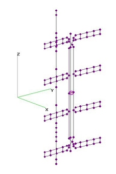
UHF 3-Bay Fat Dipole + 16 RR - OPT (21 Aug 2014)UHF 3-Bay Fat Dipole + 16 Reflector Rods analyzed using 4nec2 after determining dimensions
using nikiml's Python Optimization Scripts. Reflector Rod-to-Rod Separation was presumed
to be 2-in for an existing set of 4 ea Reflector Sub-Assemblies with 4RR each.
UHF Raw Gain = 11.8 to 12.9 dBi, F/B & F/R Ratio Min = 18.8 dB and SWR (300-ohms) under 2.9.
Hi-VHF Raw Gain FORWARD = 8 to 9 dBi on Ch9-13 and TO REAR = 6 to 8 dBi on Ch7-8 but SWR is Excessive.
[Can reduce UHF SWR under 2.7 if RS=4.8-in with only 0.3 dB Loss on 698 MHz.]
ASSUMED DIMENSIONS (all in inches):
Rdip=0.4375 = Radius of Dipole Elements (7/8-in O.D. in this model)
Rfeed=0.06425 = Radius of Feedline (AWG8 in this model)
DSwp=0 = Dipole Forward Sweep [If any, zero in this model]
Hop=1.0 = Separation at Crossovers
RR=2.0 = Reflector Rod-to-Rod Separation
Rrod=0.1875 = Radius of Reflector Rods
OPTIMIZED DIMENSIONS (rounded to nearest 1/8-inch):
DDSep=10.5 = Dipole-To-Dipole Separation
DLen=5.875 = Dipole Half-Length
FeedSep=2.75 = Separation between two FEEDLINE wires
ZCross=2.0 = From Center of Feedline Cross-Over to Center of OUTER Dipoles
RS=4.5 = Reflector Rod Separation behind Active Elements
YRod=14.875 = Reflector Rod Half-Lengths |
| 6183 Visits
24 Images
Gallery Album | |
|
 | 2.
UHF 3-Bay Fat Dipole + 12RR - OPT (20 Aug 2014)UHF 3-Bay Fat Dipole with 12 Reflector Rods analyzed using 4nec2 after determining dimensions
using nikiml's Python Optimization Scripts. Reflector Rod-to-Rod Separation was presumed
to be 2-in for an existing set of 3 ea Reflector Sub-Assemblies with 4RR each.
UHF Raw Gain = 10.9 to 12.5 dBi, F/B & F/R Ratio Min = 17.7 dB and SWR (300-ohms) under 2.7.
Hi-VHF Raw Gain Forward is low but usable on Ch7-9 & Ch13, but toward REAR is higher on Ch10-12.
Hi-VHF SWR (300-ohms) is Excessive.
ASSUMED DIMENSIONS (all in inches):
Rdip=0.4375 = Radius of Dipole Elements (7/8-in O.D. in this model)
Rfeed=0.06425 = Radius of Feedline (AWG8 in this model)
DSwp=0 = Dipole Forward Sweep [If any, zero in this model]
Hop=1.0 = Separation at Crossovers
RR=2.0 = Reflector Rod-to-Rod Separation
Rrod=0.1875 = Radius of Reflector Rods
OPTIMIZED DIMENSIONS (rounded to nearest 1/8-in):
DDSep=10.25 = Dipole-To-Dipole Separation
DLen=5.875 = Dipole Half-Length [Excludes Feedline Gap]
FeedSep=3.375 = Separation between FEEDLINE wires
ZCross=1.75 = From Center of Feedline Cross-Over to Center of OUTER Dipoles
RS=4.5 = Reflector Rod Separation behind Hourglass
YRod=13.5 = Reflector Rod Half-Lengths
ERRATA (21Aug2014): Uploaded Corrected 4nec2 File, which had "16RR" rather than "12RR" in Comments. |
| 5967 Visits
24 Images
Gallery Album | |
|
 | 3.
UHF 3-Bay FAT Dipoles + 12 Pair RR - OPT (1 Sep 2014)UHF 3-Bay FAT Dipoles with 12 Pair of Reflector Rods (narrow Gap in the middle)
analyzed using 4nec2 after determining Dimensions using nikiml's Python Optimization Scripts.
Compared to 12RR version with NO middle Gap, this version improved Raw Gain by 0.8 dB
on lowest frequencies and 0.4 dB on highest frequencies. However SWR, F/B & F/R degraded.
In Hi-VHF Band, the usable Forward Gain in the NO-MIDDLE-GAP version on Ch7-9 & Ch13 moved
to the REAR, now being consistent with Gain on other Hi-VHF Channels. SWR is still EXCESSIVE.
HOWEVER, note that when (and if) I rerun this Optimization with a revised Target Function
to hopefully adjust SWR below desired limit of 2.7, Gain advantage will no doubt shrink.
UHF Raw Gain = 11.7 to 12.9 to 12.8 dBi, F/B & F/R Min = 12.1 dB and SWR (300-ohms) under 3.1.
Hi-VHF Raw Gain = 5.9 to 7.3 dBi TO REAR, F/B & F/R Min = 6.1 dB, but SWR is EXCESSIVE.
Hi-VHF Raw Gain FORWARD is Very Poor.
ASSUMED DIMENSIONS (all in inches):
Rdip=0.4375 = Radius of Dipole Elements (7/8-in O.D. in this model)
Rfeed=0.06425 = Radius of Feedline (AWG8 in this model)
DSwp=0 = Dipole Forward Sweep [If any, zero in this model]
Hop=1.0 = Separation at Crossovers
RR=2.0 = Reflector Rod-to-Rod Separation
Rrod=0.1875 = Radius of Reflector Rods
OPTIMIZED DIMENSIONS (rounded to nearest 1/8-in):
DDSep=9.0 = Dipole-To-Dipole Separation
DLen=7.25 = Dipole Half-Length [Excludes Feedline Gap]
FeedSep=3.25 = Separation between FEEDLINE wires
ZCross=2.0 = From Center of Feedline Cross-Over to Center of OUTER Dipoles
RS=4.25 = Reflector Rod Separation behind Hourglass
YRod=17.0 = Reflector Rod Half-Lengths
Rgap=0.25 = Gap between Reflector Rod Pairs |
| 3484 Visits
21 Images
Gallery Album | |
|
 | 4.
W-G HD-4400 4-Bay Dipole - NO Reflector (5 May 2017)Winegard HD-4400 (aka PR-4400) 4-Bay Dipoles with NO Reflector Rods analyzed using 4nec2.
UHF Raw Gain - 7.5 to 10.1 dBi and SWR (300-ohms) under 3.5.
Hi-VHF Raw Gain - 4.08 to 4.15 dBi and SWR (300-ohms) = 45.6 to 3.2 is EXCESSIVE.
Based on Ken Nist's w4400.ez EZNEC model (converted to 4nec2):
http://www.hdtvprimer.com/SIMS/ |
| 78 Visits
20 Images
Shared Album | |
|
 | 5.
W-G HD-4400 4-Bay Dipole with Reflector (4 Jun2012)Winegard HD-4400 (aka PR-4400) 4-Bay Dipoles with 9 Reflector Rods analyzed using 4nec2.
UHF Raw Gain = 12.7 to 15.1 dBi, F/B & F/R Min = 11.0 dB and SWR (300-ohms) under 2.3.
Based on Ken Nist's w4400.ez EZNEC model (converted to 4nec2):
http://www.hdtvprimer.com/SIMS/ |
| 6790 Visits
14 Images
Shared Album | |
|
 | 6.
UHF 4-Bay Fat Dipoles + Grid Reflector (20 Apr 2014)UHF 4-Bay Fat Dipoles + Grid Reflector was modeled using 4nec2 file posted by kakar133 and then
modified for 3/4-Wavelenght Long Transmission Lines connected to a Common Simulated SOURCE.
UHF Raw Gain = 11.0 to 13.5 dBi, F/R & F/B Min = 17.5 dB and SWR (300-ohms) under 2.0.
Gain was significantly lower than W-G PR4400 (see 4nec2 results) and Characteristic
Impedance was only 75-ohms, requiring the use of a 1:1 Balun, e.g. Un-Equal Length Coax Balun:
http://www.hamradio.me/antennas/coax-velocity-factor.html |
| 6321 Visits
9 Images
Shared Album | |
|
 | 7.
UHF Vertical 8-Bay Dipole - NO Reflector (13 Feb 2013)UHF Vertical 8-Bay using FAT Dipoles (NO Reflector) analyzed using 4nec2.
Dimensions per Bouval's DIY posts starting with this one: http://www.digitalhome.ca/forum/showthread.php?p=1469742
Original (9.75"x9.625"): SWR Max = 3.1. Max Raw Gain = 14 dBi, but significant Gain Loss on channels in mid-40's & above.
Mod1 (6.75"x9.625"): First optimization to fix Gain Loss problem considered simply cutting off the Dipole Tube ends .
This yielded a fairly flat frequency response curve, except for some loss on lowest freqs and higher SWR on highest freqs.
Mod1: SWR Max = 3.3. Raw Gain = 9.8 dBi (470 MHz), 12.0 (674 MHz), 11.0 (698 MHz).
So a classic trade-off of Gain for wider Bandwidth. Mod1 provided higher Gain on 698 MHz than Mod2a or Mod2b below.
Mod2: Second optimization found optimum Dipole Tube length while modifying the Feedline Separation and position of
the Crossover relative to each OUTER Dipole. Bouval's Dipole-to-Dipole Separation=9.625-in was NOT changed.
By adjusting optimization parameters it is possible to influence the relative importance of Gain vs SWR:
Mod2a (7.0"x9.625"): SWR Max = 3.2. Raw Gain = 9.8 dBi (470 MHz), 12.0 (674 MHz), 11.0 (698 MHz).
Mod2b (8.0"x9.625"): SWR Max = 2.1. Raw Gain = 8.7 dBi (470 MHz), 13.2 (674 MHz), 8.7 (698 MHz).
So Mod2a provides "flattest" freq response while Mod2B provides highest Max Gain but at expense of high/low freqs.
Mod3: Third optimization found optimum Dipole Tube length while modifying the Feedline Separation and position of
the Crossover relative to each OUTER Dipole. Dipole-to-Dipole Separation was also allowed to change in this
more generalized optimization search process to compare an "optimum" configuration to the above alternatives.
To minimize Azimuthal Pattern asymmetries, Crossovers alternate as to whether Right or Left Feedline Wire
hops positive or negative on X-Axis.
Provides excellent SWR with more Gain on highest freqs to overcome extra loss in the Balun, Coax and (if used)
RF Splitter(s), although maybe more than needed for a mast-mounted Preamp with only Balun Loss a significant factor.
Mod3 (8.0"x8.5"): SWR Under 1.8. Raw Gain = 9.1 dBi (470 MHz), Max = 13.8 (686 MHz), 13.4 (698 MHz). |
| 20859 Visits
39 Images
Shared Album | |
|
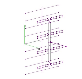
 | 8.
UHF Vertical 8-Bay Dipoles + 43RR (7 Aug 2014)UHF Vertical 8-Bay Dipole Array with 43 Reflector Rods analyzed using 4nec2 after Dimensions
determined using nikiml's Python Optimization Scripts.
UHF Raw Gain = 13.5 to 17.0 to 15.1 dBi, F/B & F/R Ratio Min = 18.3 dB and SWR (300-ohms)
under 2.4. Crossover details must be exactly copied to maintain pattern symmetry.
ASSUMED DIMENSIONS (in inches):
Rdip=0.4375 = Radius of Dipole Elements (7/8-in O.D.)
Rfeed=0.06425 = Radius of Feedlines (AWG8)
Rrod=0.1875 = Radius of Reflector Rods (3/8-in O.D.)
Hop=1.0 = X-Axis Separation at the Cross-Over
Cond=2e+07 = Conductivity for Aluminum
DSwp=0 = Dipole Forward Sweep (NOT USED IN THIS MODEL]
OPTIMIZED DIMENSIONS (in inches, rounded to nearest 1/8-in):
DDSep=9.37 = Dipole-To-Dipole Separation
DLen=6.65 = Dipole Half-Length (JUST THE TUBE)
FeedSep=2.5 = Separation between two FEEDLINE wires
ZCross=1.39 = From Center of Feedline Cross-Over to Center of OUTER Dipoles
RS=4.16 = Reflector Rod Separation behind Dipoles
RR=1.74 = Reflector Rod-to-Rod Separation
YRod=18.20 = Reflector Rod Half-Lengths |
| 4809 Visits
15 Images
Gallery Album | |
|
 | 9.
UHF Vert 8-Bay Dipole + 43 Pair RR - OPT (1 Sep 2014)UHF Vertical 8-Bay FAT Dipole with 43 Pairs of Reflector Rods analyzed using 4nec2 after
determining Dimensions using nikiml's Optimization Scripts.
For some unknown reason, Hi-VHF analysis refused to run correctly, even after trying
various AUTOSEG(xx) values.
UHF Raw Gain = 13.4 to 17.1 to 16.2 dBi, F/B & F/R Min = 14.3 dB and SWR (300-ohms) under 3.1.
Compared to NO-MIDDLE-GAP version, Raw Gain improved by an inconsequential 0.1 dB except on
the highest frequencies it improved by 0.8 dB. OTOH, hote that SWR, F/B & F/R Ratio were degraded.
HOWEVER, note that when (and if) I rerun this Optimization with a revised Target Function
to hopefully adjust SWR below desired limit of 2.7, Gain advantage will no doubt shrink.
ASSUMED DIMENSIONS (in inches):
Rdip=0.4375 = Radius of Dipole Elements (7/8-in O.D.)
Rfeed=0.06425 = Radius of Feedlines (AWG8)
Rrod=0.1875 = Radius of Reflector Rods (3/8-in O.D.)
Hop=1.0 = X-Axis Separation at the Cross-Over
Cond=2e+07 = Conductivity for Aluminum
DSwp=0 = Dipole Forward Sweep (NOT USED IN THIS MODEL]
OPTIMIZED DIMENSIONS (in inches, rounded to nearest 1/8-in):
DDSep=9.0 = Dipole-To-Dipole Separation
DLen=7.875 = Dipole Half-Length (JUST THE TUBE)
FeedSep=2.125 = Separation between two FEEDLINE wires
ZCross=1.375 = From Center of Feedline Cross-Over to Center of OUTER Dipoles
RS=4.75 = Reflector Rod Separation behind Dipoles
RR=1.5 = Reflector Rod-to-Rod Separation
YRod=16.785 = Reflector Rod Half-Lengths
Rgap=0.25 = Gap Between each Reflector Rod Pair |
| 4181 Visits
15 Images
Gallery Album | |
|
 | 10.
Winegard HD-8800 8-Bay FAT Dipoles (20 Jan 2017)Winegard HD-8800 (aka PR-8800) 8-Bay FAT Dipoles analyzed using 4nec2.
EZNEC File was downloaded from Ken Nist's HDTVPrimer, Comparing Antennas Webpage:
http://www.hdtvprimer.com/antennas/comparing.html [see SIMS link at top]
After importing into 4nec2, Ken Nist's INCORRECTLY configured Combining Feedline
was Deleted and Replaced by Dual SOURCE "EX" Statements and AutoSegmented.
Ken Niss made a mistake in the Input Feedline Structure, Incorrectly trying to Emulate what
an RF Combiner would do, resulting in wildly inaccurate SWR and hence Net Gain results.
An RF Combiner matches all Interfaces, whereas Ken's Combiner Network was a simple SHORT.
I have now fixed this problem, so Net Gain is only slightly lower than Raw Gain curve.
Note that RF Combiner has a "typical" Insertion Loss of about 0.5 dB in Hi-VHF Band and
1.0 to 1.5+ dB in UHF Band, increasing with Frequency....which REDUCES the fol. Results:
UHF Raw Gain = 13.8 to 16.5 dBi and F/B & F/R Minimum = 12.5 dB with SWR (300-ohms) Under 2.3.
Raw Gain on Upper Channels is about 1 dB more than shown in HDTVPrimer and Net Gain is MUCH
better, since SWR<2.3 results in Net Gain Loss on Ch14 of only 0.7 dB and
much less for remainder,
no doubt due to eliminating the Feedline Short.
Note that Elevation Pattern Charts showing NULL at about 40-45 degrees. |
| 1700 Visits
25 Images
Shared Album | |
| |