 | 1.
UHF Multi-Bay Comparison Charts (17 Aug 2009)Old (Ch14-69) UHF Band is from 470-806 MHz. New UHF Band is 470-698 MHz.
NOTE: Due to complexity limits in 4nec2 modeling program, most FF4 & FF6 Reflector models were forced to use
sparse Grid Size (e.g. 2"Hx2"W). If normal 1"Hx2"W Grid Size is used, F/B and F/R Ratios are significantly improved.
A. Vertically Stacked Comparisons of 2xFF6, 2xFF4, 2xM4, 2xCM4221, 2x91XG vs FF6 and three Parabolics:
i) 124-in Diameter, ii) 7-ft CM4251 and iii) Quasi-Periodic 4ea 1x1-m Reflectors driven by 8-El LPDA.
B. FF4, 91XG and Wider Bowtie Modified 91XG Performance Curves for Comparison purposes (not yet
integrated into a single Chart).
C. Multi-Bay Comparisons, presuming NO REFLECTORS and Flat Bowties (NO Forward Sweep):
C1. Compare Bowties: FF6 (Free-Form 6-Bay), A-D DB8e, FF4, CM4228HD+HHH, M4 (10.0x9.5),
FF3, M4 (9.5x9), CM4221HD (7.9x9.8), A-D DB4e, H2 (11x12), CM4221 (8.5x8.9),
Quad-Trap-Loop+2Bars and A-D C2.
C2. EV's SuperQuad (9.75x9.5) 4-Bay optimized for more Gain on low-mid UHF channels.
C3. mclapp's M4 (9.5x9.0) Super-4-Bay is not only optimized for New UHF Band, but also has low SWR
throughout Hi-VHF Ch7-13.
C4. mclapp's (9.5x9.0x8.5) per his posted 4nec2 file has improved Gain on Ch52-69, but increasing SWR
on Hi-VHF Ch7-9 degrades Net Gain.
C5. Channel Master CM4221 (8.5x8.9), per Actual measurements, is a good performer
on Old and New UHF Bands, but Hi-VHF SWR is somewhat degraded on Ch7-9.
C6. Channel Master CM4221 (7.8x8.0), per Ken Nist's measurements in CM4221a.ez EZNEC file is also a good performer
on Old and New UHF Bands, but SWR and Net Gain are severely degraded on lowest UHF and all Hi-VHF channels.
C7. UTube 4-Bay (from Babblin5 or MakeTV) is a very low performer on both UHF and Hi-VHF Bands, due to insufficient
Bowtie-to-Bowtie separation (5.75-in vs 9.0-in).
D. Multi-Bay Comparisons, presuming Screen REFLECTORS and FLAT Bowties
(Angle along centerline for SuperQuad, Outer 10-inches Angled Forward for M4 and Flat for CM4221) and Flat Bowties:
D1. EV's SuperQuad (9.75x9.5) 4-Bay optimized for more Gain on higher UHF channels.
D2. mclapp's M4 (9.5x9.0) Super-4-Bay is not only optimized for New UHF Band, but also 7.0-3.0 dBi Net Gain
across the Hi-VHF Band, with lowest SWR on Ch7.
D3. Channel Master CM4221 (8.5x8.9), per Actual measurements is a good performer on Old and especially New UHF Bands,
but Hi-VHF SWR and Net Gain are seriously degraded, esp on Ch7-9. Hi-VHF Gain is 3.5 to 6.5 dB HIGHER
towards the REAR than the FRONT.
D4. Channel Master CM4221 (7.8x8.0), per Ken Nist's measurements in CM4221a.ez EZNEC file is a good performer
on Old and New UHF Bands, but SWR and Net Gain are severely degraded on lowest UHF and all Hi-VHF channels.
E. Multi-Bay Comparisons, presuming Screen REFLECTORS and SWEPT Bowties
(Angle along centerline for SuperQuad, Outer 10-inches Angled Forward for M4 and Flat for CM4221) and Flat Bowties:
E1. EV's SuperQuad (9.75x9.5) 4-Bay optimized for more Gain on higher UHF channels.
E2. mclapp's M4 (9.5x9.0) Super-4-Bay is also optimized for New UHF Band with more gain on lower UHF channels.
Both antennas suffered from excessive SWR in the Hi-VHF Band.
F. Combiner Mod for Old CM4228 compared to original crossover between the two 4-Bay stacks. Also compared to various
4-Bay antennas. Above Ch51: Significant improvement. Lowest UHF channels: 3 dB improvement in Raw Gain but only
minor improvement in Net Gain due to poor SWR.
G. New CM4228HD (As Shipped) was much better than old CM4228 on the (problematic) lowest channels,
but had 1-2 dB lower Gain above Ch30.
New CM4228HD was actually somewhat worst than mclapp M4 Super-4-Bay, esp on lowest channels.
H. Combiner Mod for New CM4228HD compared to "As Shipped" to illustrate how much is lost in the horizontal interconnect.
If a low loss RF Combiner Module is used (not an easy task), more than 2 dB of improvement MIGHT be possible...
CM4228HD with Hollands Horizontal Harness (HHH) Mod, essentially MATCHES the RF Combiner Mod UHF Band improvements.
I. Compared fol. 2-Bays+11RR: Triangles, H2 Bowties, Quad-Traps, Bi-Quads, Twin-Loops and Hourglass-Loops.
J. Compared fol. 2-Bay Bowties w/o Reflector: mclapp M2 (9.5x9.0), M2 (10.0x9.5) and the OPTIMIZED H2 (12x11),
with significantly better UHF and Hi-VHF performance. |
| 53493 Visits
59 Images
Gallery Album | |
| |
|
| |
|
|
 | 4.
UHF 2-Bay SOLID Triangles - Var RR's (4 Mar 2015)UHF 2-Bay SOLID Triangles (and Other Shapes) with Various Reflector Rods analyzed using 4nec2
after determining dimensions using nikiml's Python Optimization Scripts.
Three versions were analyzed: SOLID Triangles, SOLID FAT Triangles and SOLID Pennants.
Latter two prelim "bestx_xxx.nec file results were found while the Optimizer searched
for the OPTIMUM SHAPE, presuming a Generic Octagonal Outline....but performance was
a bit LESS than a simple Triangle. Charts show Excellent UHF and Hi-VHF performance for
All Triangles (and H2) compared to various other 2-Bay variations...although with narrower Beamwidths.
a) 2-Bay (9.25x12.5) SOLID Triangles + 11RR:
UHF Raw Gain = 12.7 to 14.9 dBi, F/B & F/R Min. = 20.8 dB and SWR (300-ohms) under 1.9.
Hi-VHF Raw Gain = 8.1 to 8.3 dBi, F/B & F/R = 13.9 to 17.9 dB and SWR (300-ohms) = 88 to 36 is Excessive.
SUMMARY OF DIMENSIONS:
BowLength=9.25-in, BowSpacing=12.5-in,
TineSep=7.5-in, FeedSep=4.0-in,
ALL Elements and Feedline Wire Size = AWG10.
Reflector Rod Wire Size = 0.125-in = QICT, Quarter-Inch Copper Tubing,
Reflector Rod Separation behind Hourglass) = RS = 4.0-in,
Reflector Rod-to-Rod Separation = RR = 2.25-in,
Reflector Rod Half-Lengths = YRod = 18.625-in.
====================================
b) 2-Bay SOLID FAT Triangles + 11RR [with Optimized Generic Octagonal Shape]:
USB Raw Gain = 12.2 to 14.4 to 14.3 dBi, F/B & F/R Ratio Min. = 20.8 dB and SWR (300-ohms) under 2.4.
Hi-VHF Raw Gain = 7.7 to 7.9 dBi, F/B & F/R Ratio = 13.7 to 18.6 dB and SWR (300-ohms) = 86 to 38 is Excessive.
====================================
c) 2-Bay SOLID Pennants + 11RR [with Optimized Generic Octagonal Shape]:
UHF Raw Gain = 12.2 to 14.5 dBi, F/B & F/R Ratio Under 18.8 dB and SWR (300-ohms) Under 1.8.
Hi-VHF Raw Gain = 7.8 to 7.9 dBi, F/B & F/R = 13.7 to 19.4 dB and SWR (300-ohms) = 96 to 38 is Excessive. |
| 28731 Visits
69 Images
Gallery Album | |
| |
|
| |
| 6.
UHF 4-Bay Bowties - NO Reflectors (February 26, 2009)4-Bay Bowtie Antennas (If NO Reflectors and Flat Bowties) analyzed for VHF and UHF performance using 4nec2.
Compares (way too small) U-Tube/MakeTV, an unknown 4-Bay, CM-4221, MClapp's Supersized M4 and EV's Kosmic SuperQuad antennas.
Navigate up one level to "Multi-Bay Antennas" for additional Comparison Charts.
EDIT (24Aug2009): Added CM4221 runs using ACTUAL MEASUREMENTS as verified against a photo posted by mclapp.
UTube results were revised due to calculation error in the 4nec2 model. |
| 15 Albums
Shared Folder | |
| |
| 7.
UHF 4-Bay Bowties with Reflector (August 17, 2009)4-Bay Bowtie Antennas with Screen Reflector analyzed using 4nec2.
Navigate UP one level to "Multi-Bay Antennas" for additional Comparison Charts. |
| 21 Albums
Shared Folder | |
| |
| 8.
UHF H4 2x2-Bay Bowties (2 Mar 2013)| UHF Horizontal 4-Bay (H4), 2x2-Bay Bowtie Antennas analyzed using 4nec2. |
| 4 Albums
Shared Folder | |
|
 | 9.
HiVHF+UHF HUM4 (9.5x9) + 2Sizes ReflRods (9 Jan 2014)Hi-VHF + UHF HUM4 (9.5x9-in) with 2 Sizes of Reflector Rods (RR) analyzed using 4nec2.
Nikiml's new CMD--OPT Python Script Optimization commands are now embedded in 4nec2 Files,
where the fol. is the contents of the *.bat Python Control File (your's may vary):
cd c:\Python27
python -m nec.opt --num-cores=7 HUM4_9-5_9_BS0_4+7RR-2Sizes_PY.nec
pause
Two examples are shown, a sparse lower performance model and a medium performance model
where I chose the number of RR's for roughly equal F/B Ratio in each Band out of the
twelve I've run thus far. Note there are about TWICE as many UHF RR's as for Hi-VHF.
(More runs are planned, esp. with more RR's.)
Hi-VHF SWR is just a bit over desired 2.7 target, which I could fix by adjusting
Target Function to increase the "importance" (multiplier) for the "max_ml" term.
But instead I ran a Parameter Sweep for RS (Hi-VHF Rod-to-Bowtie Separation),
allowing a user to PICK whether they want MORE GAIN (smaller RS) or BETTER SWR (larger RS).
===========================================================
a) HUM4+4RR+7RR with 4-RR for Hi-VHF and 7-RR for UHF:
Bowtie-to-Hi-VHF-RR Separation RS=13.0
Bowtie-to-UHF-RR Separation-in RS2=5.5-in
UHF Raw Gain = 10.3 to 13.7 dBi, F/B & F/R Ratio Min = 11.9 dB and SWR (300-ohms) Under 2.4.
Hi-VHF Raw Gain = 6.4 to 7.0 to 6.7 dBi, F/B & F/R Ratio Min = 13.3 dB and SWR (300-ohms) Under 3.4.
===========================================================
b) HUM4+8RR+15RR with 8-RR for Hi-VHF and 15-RR for UHF:
Bowtie-to-Hi-VHF-RR Separation RS=13.0 [Or 14.5-in to push Hi-VHF SWR under 2.8 with 0.5 dB Gain reduction.]
Bowtie-to-UHF-RR Separation-in RS2=5.5-in
UHF Raw Gain = 11.9 to 14.9 to 14.5 dBi, F/B & F/R Ratio Min = 15.3 dB and SWR (300-ohms) Under 2.5.
Hi-VHF Raw Gain = 6.6 to 7.5 to 7.2 dBi, F/B & F/R Ratio Min = 15.1 dB and SWR (300-ohms) Under 3.2.
c) T.B.D. |
| 9821 Visits
42 Images
Shared Album | |
|
 | 10.
NEW UHF FF6 No Refl - OPT (26 Aug 2017)NEW-UHF [470-608 MHz] Free-Form 6-Bay Bowtie (FF6) with NO Reflector Analyzed using
4nec2 after determining BEST Dimensions using nikiml's Python Optimization Scripts.
New UHF Band Raw Gain = 12.2 to 14.0 dBi with SWR (300-ohms) under 2.5.
Hi-VHF Raw Gain = 5.8 to 4.6 dBi with SWR (300-ohms) = 3.3 to 2.6 to 3.5 is a bit High.
DIMENSION STATEMENTS: [May Round to nearest 1/4-in]
' Radius (in inches) of BOWTIE elements:
SY Rbow=0.051 [AWG10]
' Radius (in inches) of FEEDLINE wires:
SY Rfeed=0.051 [AWG10]
' Separation at Crossover:
SY Hop=1.0
' Conductivity (Copper=3.0e7, Alum=2.0e7, StainlessSteel=1.67e7:
SY Cond=3e+07
' Distance between the centers of the two INNER bowties:
SY ZBowII=14.18
' From center of INNER bowtie to center of OUTER bowtie:
SY ZBowOI=12.41
' From center of OUTER bowtie to center of EXTERIOR bowtie:
SY ZBowOE=10.53
' INNER Bow Whisker Length (lose some in bend):
SY BowLeni=13.27
' OUTER Bow Whisker Length (lose some in bend):
SY BowLeno=9.37
' EXTERIOR Bow Whisker Length (lose some in bend):
SY BowLenE=8.95
' INNER Bow Forward Sweep distance at tip of the whisker:
SY BowSwpi=0.0 [Not used in this Model]
' OUTER Bow Forward Sweep distance at tip of the whisker:
SY BowSwpo=0.0 [Not used in this Model]
' EXTERIOR Bow Forward Sweep distance at tip of the whisker:
SY BowSwpE=0.0 [Not used in this Model]
' INNER Bow Tine Separation:
SY TineSepi=8.38
' OUTER Bow Tine Separation:
SY TineSepo=6.91
' EXTERIOR Bow Tine Separation:
SY TineSepE=5.61
' Separation between two FEEDLINE wires: [CONSTRAINT: TRY ALL THE SAME.]
SY FeedSep=3.11
' From center of Feedline Cross-Over to center of OUTER Bowtie:
SY ZCross=1.25
' From center of Feedline Cross-Over to center of EXTERIOR Bowtie:
SY ZCrossE=2.32
UPDATE (17Aug2019): Added Dimension Statements. |
| 3578 Visits
31 Images
Shared Album | |
|
 | 11.
NEW UHF Free-Form 6-Bay (NU-FF6) + VDAR (26 Aug 2017)NEW-UHF [470-608 MHz] Free-Form 6-Bay (NU-FF6) Bowtie Antennas with 60"Hx36"W VDAR
(Variable Double Angle Reflector, 2x2" Grid) analyzed using 4nec2. Dimensions were Optimized
using nikiml's Python Scripts.
NEW UHF Band Raw Gain = 15.2 to 17.8 dBi, F/R & F/R Ratio Min. = 21.0 dB and SWR (300-ohms) Under 2.1.
Hi-VHF Raw Gain = 13.7 to 8.9 dBi, F/B & F/R Ratio Min = 13.9 dB and SWR (300-ohms) = 5 to 21 is Excessive.
Compared to OLD UHF Band FF6, we see 1.8 dB Gain increase on 608 MHz, but 0.2 dB Loss on 470 MHz
with significant increase in Hi-VHF Band Gain:
UHF = 15.0 to 16.4 to 16.0 to 17.0 dBi, F/B & F/R Ratio Min = 15.2 dB and SWR (300-ohms) Under 1.7.
Hi-VHF Raw Gain = 9.1 to 8.0 dBi, F/B & F/R Ratio Min = 14.1 dB and SWR (300-ohms) = 17 to 13 is Excessive:
https://imageevent.com/holl_ands/multibay/uhf6baybowtievdar
EDIT (7May2019): Added comparison to Old UHF Band FF6. |
| 4764 Visits
20 Images
Shared Album | |
|
 | 12.
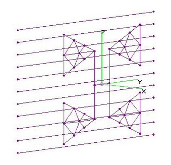
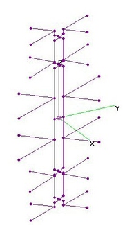
UHF FF6 Vertical 6-Bay Bowtie - NO Refl (11 Dec 2014)UHF Vertical 6-Bay Bowtie (FF6) with NO Reflector analyzed using 4nec2 after finding
best Dimensions using nikiml's Python Optimization Scripts.
UHF Raw Gain = 11.0 to 14.5 dBi and SWR (300-ohms) under 2.9.
Hi-VHF Raw Gain = -4.2 to 5.8 to 5.5 dBi and SWR (300-ohms) = 21 to 3.1.
ASSUMED DIMENSIONS (All in inches):
Rbow=0.051 = AWG10 Element Wire size [AWG12 thru AWG8 are also good]
Rfeed=0.051 = AWG10 Feedline Wire size [AWG12 thru AWG8 are also good]
Hop=1.0 = X-Axis Separation at Crossover
OPTIMIZED DIMENSIONS (All in inches, may round to nearest 1/8-in):
ZBowII=13.07 = Distance between the Centers of the two INNER Bowties
ZBowOI=11.13 = From Center of INNER Bowtie to Center of OUTER Bowtie
ZBowOE=9.02 = From Center of OUTER Bowtie to Center of EXTERIOR Bowtie
BowLeni=11.63 = INNER Bow Whisker Length (lose some in bend)
BowLeno=7.71 = OUTER Bow Whisker Length (lose some in bend)
BowLenE=7.82 = EXTERIOR Bow Whisker Length (lose some in bend)
TineSepi=7.57 = INNER Bow Tine Separation
TineSepo=5.60 = OUTER Bow Tine Separation
TineSepE=3.57 = EXTERIOR Bow Tine Separation
FeedSep=3.33 = Separation between two FEEDLINE wires
ZCross=2.18 = From Center of Feedline Cross-Over to Center of OUTER Bowtie
ZCrossE=3.01 = From Center of Feedline Cross-Over to Center of EXTERIOR Bowtie |
| 11191 Visits
19 Images
Shared Album | |
|
 | 13.
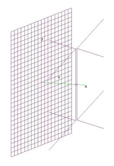
UHF Vertical 6-Bay Bowtie (FF6) + VDAR (29 Sep 2015)UHF Vertical Free-Form 6-Bay Bowtie (FF6) with Variable Double Angle Reflector (VDAR) Analyzed using 4nec2.
Two versions are analyzed, with only minor differences between them:
===================================
a) FF6 (all 19 Variables Searched for Optimum) with Variable Double Angled Reflector (VDAR) (60"Hx36"W),
assuming Grid=2"Hx4"W [F/B & F/R Ratios improve if use 1"Hx2"W]:
UHF = 15.0 to 16.4 to 16.0 to 17.0 dBi, F/B & F/R Ratio Min = 15.2 dB and SWR (300-ohms) Under 1.7.
Hi-VHF Raw Gain = 9.1 to 8.0 dBi, F/B & F/R Ratio Min = 14.1 dB and SWR (300-ohms) = 17 to 13 is Excessive.
===================================
b) One-Half of Separately Optimized Horiz-Stack 2xFF6's each with VDAR (60"Hx36"W),
assuming Grid=2"Hx4"W [F/B & F/R Ratios improve if use 1"Hx2"W]:
UHF Raw Gain = 14.7 to 16.7 to 16.3 to 16.8 dBi, F/B & F/R Ratio Min = 16 dB and SWR (300-ohms) Under 1.7.
Hi-VHF Raw Gain = 10.1 to 8.4 dBi, F/B & F/R Ratio Min = 15.4 dB and SWR (300-ohms) = 5.6 to 16.2 to 14.0
is Excessive.
EDIT (23Mar2016): Added Dimensioned Drawing for Bowtie Portion of FF6+VDAR, version (a).
Instructions for VDAR is "Angled Reflector" found on mclapp's website:
http://m4antenna.eastmasonvilleweather.com/Drawings/PDF%20Drawings.html |
| 10981 Visits
51 Images
Shared Album | |
| |
|
| |
|
|
 | 16.
Hi-VHF 2-Bay Bowtie - NO Reflector (1 Apr 2010)Hi-VHF 2-Bay Bowtie analyzed using 4nec2 to find "quasi-optimized" dimensions.
a) For Best overall performance use following Dimensions [44" H x 61" W]:
BowLength=30in, BowSeparation=29in, TineSeparation=15in,
FeedlineSeparation=3.0-in and ALL AWG10 (or larger) wire size.
Hi-VHF Raw Gain = 6.7 to 9.3 dBi and SWR (300-ohms) Under 2.6.
==================================
b) To MINIMIZE Hi-VHF SWR at expense of Hi-VHF Gain and even worse Lo-VHF SWR:
BowLength=27in, BowSeparation=26in, TineSeparation=13.5in,
FeedlineSeparation=3.0-in and ALL AWG10 wire size.
Hi-VHF Raw Gain = 5.7 to 8.1 dBi and SWR (300-ohms) Under 1.7.
==================================
c) Following dimensions are a compromise, maximizing Hi-VHF Gain and Lo-VHF SWR at the expense
of a slightly higher Hi-VHF SWR. Quasi-Optimum sizes for ALL AWG10 Wire sizes (49-in H x 66-in W):
BowLength=33in, BowSeparation=32in, TineSeparation=17in,
FeedlineSeparation=1.5-in and ALL AWG10 wire size.
Hi-VHF Raw Gain = 7.6 to 10 dBi and SWR (300-ohms) Under 3.5 [EXCESSIVE].
Performance in UHF Band was also analyzed...yes, there is Gain, but it is very inconsistent in beam direction.
==================================
UPDATE (6Jul2016): Expanded (29x30) alternative and moved up to first (preferred) position. |
| 35254 Visits
33 Images
Shared Album | |
|
 | 17.
HiVHF 2-Bay - Various Reflector Rods (7 Mar 2013)Hi-VHF 2-Bay Bowtie Antennas with Various Number of Reflector Rods analyzed using 4nec2.
a) Hi-VHF 2-Bay Bowtie with 18 Reflector Rods has unusually high F/B Ratio. Size = 48.75-in H x 59.5-in W.
Bowtie dimensions were taken from the Optimized NO Refl. version. ALL Reflector Rod parameters
were variables in nikiml's Python Optimization Scripts.
Hi-VHF Raw Gain Max = 11 to 13 dBi, Hi-VHF F/B & F/R Ratio Min = 20.2 dB and SWR (300-ohms) under 2.3.
BowLength=33-in (AWG10 Elements), BowSpacing=32-in, TineSep=17.0-in, FeedSep=1.5-in (AWG10).
Reflector Rod sets are CENTERED behind each Bay, with a Rod directly behind each Bay.
Reflector Rod Separation behind Center of Bowties: RS=15.5, Reflector Rod-to-Rod Separation: RR=3.5,
Reflector Rod Half-Lengths: YRod=48.75, Reflector Rod Radius (1/4-in Diameter): Rrod=0.125.
b) Hi-VHF 2-Bay Bowtie with 10 Reflector Rods has moderate F/B Ratio.
Bowtie dimensions were taken from the Optimized NO Refl. version. ALL Reflector Rod parameters
were variables in nikiml's Python Optimization Scripts. Size = 42.875-in H x 58.5-in W.
Hi-VHF Raw Gain = 10.9 to 13.1 dBi, Hi-VHF F/B & F/R Ratio Min = 15.3 dB and SWR (300-ohms) under 2.4.
BowLength=33-in (AWG10 Elements), BowSpacing=32-in, TineSep=17.0-in, FeedSep=1.5-in (AWG10).
Reflector Rod sets are CENTERED behind each Bay, with a Rod directly behind each Bay.
Reflector Rod Separation behind Center of Bowties: RS=14.25, Reflector Rod-to-Rod Separation: RR=6.5,
Reflector Rod Half-Lengths: YRod=42.875, Reflector Rod Radius (1/4-in Diameter): Rrod=0.125. |
| 10698 Visits
24 Images
Shared Album | |
|
 | 18.
Hi-VHF 2-Bay Bowtie - FLAT Grid Refl. (16 Apr 2010)Hi-VHF 2-Bay Bowtie with 56"Hx72"W Flat Reflector (2"Hx4"W Grid) analyzed using 4nec2.
Bowtie Dimensions:
BowLength=33-in, BowSpacing=32-in, TineSep=17.0-in (AWG10 Elements).
Feedline: AWG10 FeedSeparation=1.5-in, Crossover Hop=0.5-in.
ERRATA (15Feb2011): Replaced 4nec2 file, because first comment line said "Super-4-Bay" instead of "2-Bay". No other changes. |
| 11499 Visits
20 Images
Shared Album | |
|
 | 19.
Hi-VHF FF4 4-Bay Bowtie - NO Reflector (7 Jul 2016)Hi-VHF Free-Form 4-Bay Bowtie (FF4) with No Reflector analyzed using 4nec2 after determining
"best" Dimensions for AWG10 Wire Size using nikiml's Python Optimization Scripts.
See 4nec2 File for Dimensions. Total Size = 114.7-in H x 65.9-in W:
Hi-VHF Raw Gain = 10.4 to 12.6 dBi with SWR (300-ohms) Under 2.7. |
| 5449 Visits
18 Images
Shared Album | |
|
 | 20.
Hi-VHF 4-Bay Bowtie - NO Reflector (1 Apr 2010)Hi-VHF 4-Bay Bowtie analyzed using 4nec2, for a Uniform 4-Bay (No Reflector) with SAME Dimensions for
Whisker Length, Bowtie-Bowtie Separation and Tine Separations using AWG10 wires, presuming AWG10 Wire Size.
Two versions are presented:
a) nikiml's Python OPTImization Scripts were used to find the "best" Dimensions:
BowLength=30.5-in, Bowtie-Bowtie Separation=31.5-in, TineSeparation=17.5-in, Feedline Separation=1.0in
and Hop Separation=1.0-in at the OFFSET Crossovers, which are 7.5-in from OUTER Bowties:
Total Size = 112-in H x 59.4-in W:
Hi-VHF Raw Gain = 10.2 to 12.3 dBi and SWR (300-ohms) Under 2.2.
========================================================
b) BowLength=33-in, Bowtie-Bowtie Separation=32-in, TineSeparation=17-in, Feedline Separation=1.5-in
and Hop Separation=0.5-in at the Crossovers. A very long crossover was assumed (like Kosmic SuperQuad
vice Offset Crossover in CM4224).
Total Size = 113-in H x 66-in W:
Hi-VHF Raw Gain = 11.0 to 12.3 to 10.8 dBi and SWR (300-ohms) Under 3.0 [HIGHER than Desired].
Performance in UHF Band was also analyzed. Yes there is Gain, but it is very inconsistent in beam direction.
ERRATA (7Jul2016): Original 2010 Gain Curve was corrected (F/B & F/R Ratios should have been Zero).
Due to small differences (couple tenths of a dB), decided to rerun and upload ALL Hi-VHF Band Results.
UPDATE (9Jul2016): Added an OPTIMIZED version (First Alternative) with Acceptable SWR. |
| 11807 Visits
40 Images
Shared Album | |
|
 | 21.
Hi-VHF 4-Bay Bowtie with Reflector Hi-VHF 4-Bay Bowties with 15 and 25 Reflector Rods analyzed using 4nec2.
Whisker Length = 31-in (QICT) , Bowtie Separation = 32-in, Tine Separation = 17-in.
Feedline Separation = 1.5-in (QICT), Crossover = 5-in from Outer Bowties.
15 (or 25) Reflector Rods (QICT) with 10-in (or 5-in) Separation, Width = 40-in, Total Height = 60-in.
Distance from Reflector Rods to Bowties = 15-in.
QICT = Quarter Inch Copper Tubing (or 3/8-in Aluminum Tubing), smaller diameter increases SWR a bit,
with AWG8 preferred over AWG10. Could also use RG-6/58/59 Coax (for Hi-VHF, no need to strip insulation).
Size (with 15-Reflector Rods) was optimized for max Gain=15.5 dBi on Ch13, 13.1 dBi Gain on Ch7 and SWR under 2.0.
Size (with 25-Reflector Rods) was optimized for max Gain=15.9 dBi on Ch13, 13.6 dBi Gain on Ch7 and SWR under 2.3.
A slightly larger size (1 to 2-in more) would improve Ch7 with some Gain reduction on Ch13. |
| 15368 Visits
28 Images
Shared Album | |
| |