 | 1.
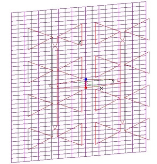
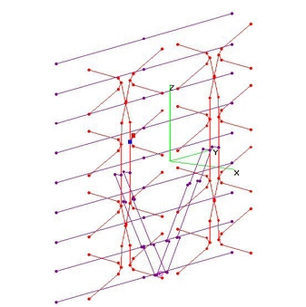
New CM4228HD (As Shipped) (28 Aug 2010)New CM4228HD (As Shipped) analyzed using 4nec2. I obtained measurements directly from a recently delivered antenna.
Note that Ken Nist (of HDTVPrimer) determined that the Printed Circuit Board (PCB) Balun ATTENUATED Hi-VHF Gain by 3 dB,
which is NOT included in below results. This can be avoided if the PCB Balun is replaced by a conventional 4:1 Balun Transformer.
Choice of AutoSegmentation value (typ. 7 or 11) was very critical to finding a "workable" solution and was different for UHF & Hi-VHF.
BowLength = 8.0-in, Bowtie Spacing = 8.0-in, Tine Separation = 4.75-in. Approx. AWG6 wire size (0.157" O.D.).
Feedline Separation = 1.3-in, with 0.5-in Hop at Crossover. AWG9 wire size (0.118" O.D.).
Center of Crossovers 1.5-in from Center of Outer Bowties. Left to Right Bay Separation = 20-in.
16 each AWG4 (0.2-in O.D.), 40-in long Reflector Rods, at 4-in separation (32-in Total Height). Separation from Bowties = 4.4-in.
UHF Gain is about 14 dBi on most channels, dropping to 10.5 dBi on Ch14. Excellent SWR under 2.0.
Hi-VHF Gain is very uneven with Excessive SWR on most channels, but remains pointed in the Forward direction.
Charts are included comparing CM4228HD (As Shipped) to older CM4228, as well as comparisons
to mclapp's M4 Super-Sized 4-Bay and CM4228/CM4228HD with & w/o RF Combiner Mod.
New CM4228HD (As Shipped) was much better than old CM4228 on the (problematic) lowest channels,
but had 1-2 dB lower Gain above Ch30.
New CM4228HD was actually somewhat worst than mclapp M4 Super-4-Bay, esp on lowest channels.
Sweeping the TIPS of the Bowties directly forward by (optimum) 1-inch provided only up to 1 dB of Gain improvement
at the expense of up to 2 dB of reduction in F_B and F_R Ratios. So might not be worth it.
Modifying the vertical Tine Separation between the TIPS of the Bowties by (optimum) of 2-inch separation resulted in
only up to 1 dB Gain increase at mid and high channels and up to 3 dB on lowest channels. On-Air Tests are needed to verify.
Combiner Mod for New CM4228HD compared to "As Shipped" to illustrate how much is lost in the horizontal interconnect.
If a low loss RF Combiner Module is used (not an easy task), more than 2 dB of improvement MIGHT be possible....
Bear in mind that an RF Combiner Module will have AT LEAST 0.5 dB Loss (and likely more on higher freqs) not shown
in the charts, see actual RF Splitter/Combiner measurements at www.antennahacks.com (back-to-back tests, so divide by 2).
NOTE: The Autosegment feature of 4nec2 was used to determine how many wire segments to use when modeling each wire element.
The choice of Autosegment=11 was very critical in getting the CM-4228HD Gain and SWR calculations to work AT ALL.
And small changes to Autosegment resulted in large changes in Hi-VHF Gain & SWR....so Hi-VHF results might not be all that accurate.
EDIT (29Mar2013): Added (Slides 16-21) ANOMALOUS plots versus Bowtie Tine Separation and
Bowtie Forward Sweep, which can frustrate finding an "Optimum" set of dimensions.
I believe that this is a 4nec2 Modeling anomaly, rather than inherent in CM4228HD design.
There's NO WAY Whisker movements of a couple thousandths of an inch result in BIG Gain changes.
Also added (Slide 39) ANOMALOUS Small Perturbation Test Results showing Raw Gain varies as much
as +/- 1.0 dB when Bowtie Tine Separation and Bowtie Forward Sweep are Randomly Perturbed
by up to +/- 0.25-in, using EXCEL's 0.0001*RANDBETWEEN(-2500,2500) function to generate variables.
Indicates that Raw Gain at 470 MHz may actually be closer to 13.0 dBi than 10.5 dBi found in
"unperturbed" 4nec2 Model. |
| 16396 Visits
45 Images
Shared Album | |
|
 | 2.
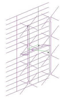
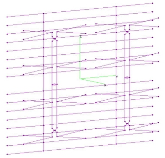
CM4228HD with UHF Hollands Horiz Harness (26 May 2014)New CM4228HD (8" Whiskers x 8" Spacing) with Hollands Horizontal Harness (HHH) replacing the Original Harness analyzed using 4nec2.
Dimensions of HHH OPTIMIZED using nikiml's Python Control Scripts were the WIDTH of the Feedline and X-Axis SEPARATION
from the Center of the Bowties, similar to 2x2 4-Bay (H4) as well as the Vertically Stacked 4-Bay Antenna designs.
Optimized Dimensions:
Xh = - 2.60-in = Separation between Feedlines and Center of Bowties.
Diagonal Wire Lengths, Harness to Feedline = 3.18-in (Top-Left & Bottom-Right) AND = 2.84-in (Bottom-Left & Top-Right).
Yinner = 10.80-in = Y-Axis Distance from Harness to INNER Bowtie Feedline (Top-Left & Bottom-Right).
Youter = 10.85-in = Y-Axis Distance from Harness to OUTER Bowtie Feedline (Bottom-Left & Top-Right).
[Since difference of +/- 1/8-inch won't make much difference in performance, can round Harness Wire
Half-Lengths to 8.75-in and Diagonal Wire Lengths to 3.0-in, demonstrating there was no need for separate SYmbols.]
UHF Raw Gain = 15.0 to 14.9 to 16.5 dBi, F/B & F/R Ratio Min = 19.1 dB and SWR (300-ohms) Under 2.3.
These are significant improvements over the AS-SHIPPED CM4228HD version.
Hi-VHF Raw Gain = 4.3 to 12.9 dBi and SWR (300-ohms) = 14.2 to 9.8 to 61.9 is Excessive.
PS: Views with Reflector Removed are included to facilitate seeing the HHH. Note that Optimizer determined Harness
Wire Lengths, rather than constraining them to be 1/2 the Bay Separation, as presumed in some OTHER HHH designs.
=====================================================
Parametric Sweeps (Calculate/Start Optimizer in 4nec2) were used to investigate sensitivity
to changes in HHH Dimensions (see Images 44+).
Raw Gain and SWR were very insensitive to changes in either Gap, Xh, Youter=Yinner
or Rharn with only a few tenths of change to SWR and only a few tenths of a dB change to
F/B & F/R Ratios over the fairly wide range of HHH dimensions tested.
=====================================================
ERRATA (12Jul2014): Typo found in above text (HHH Diagram showed correct values).
Yinner = Youter = 10.8+ inches (NOT 8.8-in).
EDIT (12JUL2014): Added Parametric Sweeps to investigate HHH sensitivity to changes.
EDIT (5Apr2016): Added missing (2.84") Dimension for Upper Left Short Diagonal Wire in HHD Dimensional Drawing.
EDIT (20Mar2017): Added Tine Separation to HHH Dimensional Drawing. Added "UHF" to Labels to emphasize
that THIS HHH Version was Optimized for UHF-ONLY, to differentiate from newer Hi-VHF/UHF HHH's.
EDIT (3Apr2017): Added Elevation Pattern Charts showing NULL at about 40-45 degrees. |
| 5868 Visits
47 Images
Shared Album | |
|
 | 3.
Hi-VHF+UHF CM4228HD HHH - ALTERNATIVES (5 Feb 2017)Hi-VHF & UHF COMBO CM4228HD with Holl_ands Horizontal Harness (HHH) Mod and various other
Modifications Re-Optimized to improve SWR in Hi-VHF Band, using nikiml's Python Optimization
Scripts and EVAL Function to Calculate "Best" Performance.
There are significant Hi-VHF improvements over AS-SHIPPED CM4228HD version plus HHH [Jun2014 Version]:
UHF Raw Gain = 15.0 to 14.9 to 16.5 dBi, F/B & F/R Ratio Min = 19.1 dB and SWR (300-ohms) Under 2.3.
Hi-VHF Raw Gain = 4.3 to 12.9 dBi and SWR (300-ohms) = 14.2 to 9.8 to 61.9 is Excessive.
For details: http://imageevent.com/holl_ands/multibay/8bayrefl/newcm4228hdwithhollandshorizharness
Four Alternatives were considered. Overall, (d) was BEST with (c) NEXT BEST, with significant
reduction in Hi-VHF F/B Ratio. Version (b) was also Very Good, except for DEEP DIP in Hi-VHF F/R Ratio on Ch10/11:
Detailed Dimensional Drawings for HHH Versions are at bottom of this Webpage.
Note that CM's Original PCB (Printed Circuit Board) Balun is UHF-ONLY and MUST BE REPLACED
with a conventional, cylindrical 300:75-ohm Transformer Balun, which passes both Hi-VHF and UHF.
a) Re-Optimize HHH Dimensions as well as Tine Separation (TS), because it's easy for user to change:
UNSTABLE and VERY BAD ANYWAY....so will NOT Post.
======================================
b) Re-Optimize HHH Dimensions as well as Tine Separation (TS) and Reflector-to-Bowtie Separation (RS):
Good Overall Performance, except for Deep DIP in Hi-VHF F/R Ratio Performance on Ch10/11:
UHF Raw Gain = 15.2 dBi +/- 0.2 dB, F/B & F/R Ratio Minimum = 18.6 dB and SWR (300-ohms) Under 2.1.
Hi-VHF Raw Gain = 8 dBi +/- 1 dB, F/B & F/R Ratio Minimum = 5.6 dB and SWR (300-ohms) Under 1.6.
Hi-VHF F/B & F/R Ratios = 13.6 to 20 dB EXCEPT on Ch10 they dive to only 5.6 dB.
======================================
c) Re-Optimize HHH Dimensions as well as Tine Separation (TS), Reflector-to-Bowtie Separation (RS)
and Wider Reflector Rod Width (+/- Yrod):
UHF Raw Gain Slightly Better than other Versions and Hi-VHF Raw Gain is Second Best:
UHF Raw Gain = 15.5 dBi +/- 0.8 dB, F/B & F/R Ratio Minimum = 17.5 dB and SWR (300-ohms) Under 2.1.
Hi-VHF Raw Gain = 8.5 dBi +/- 0.5 dB, F/B & F/R Ratio Minimum = 11.7 dB [Moderate] and SWR (300-ohms) Under 1.3.
======================================
d) Re-Optimize HHH Dimensions as well as Tine Separation (TS), Reflector-to-Bowtie Separation (RS)
and Overall Reflector Rod Length (+/- Yrod) for ALTERNATING Reflector Rods:
UHF Raw Gain Slightly Better than other Versions and Hi-VHF Raw Gain and F/R Ratio are BEST:
UHF Raw Gain = 15.4 dBi +/- 0.6 dB, F/B & F/R Ratio Minimum = 17.0 dB and SWR (300-ohms) Under 2.7.
Hi-VHF Raw Gain = 8.6 dBi +/- 0.3 dB, F/B & F/R Ratio Minimum = 17.5 dB [Very Good] and SWR (300-ohms) Under 1.7.
UPDATE (19Mar2017): Uploaded Performance Comparison Charts, incl. Minor Updates to TS+RS
Version uploaded earlier, New Images and HHH Dimensional Drawings for two "BEST" Hi-VHF + UHF Versions.
UPDATE (20Mar2017): Uploaded Dimensional Drawing for Alt(b). |
| 2269 Visits
28 Images
Shared Album | |
|
 | 4.
CM4228HD with RF Combiner Mod (28 Aug 2010)CM4228HD with RF Combiner Modification (RCM) analyzed using 4nec2 . The Horizontal Interconnect Harness between the
two 4-Bays is replaced by a Balun at the center drive point of each 4-Bay, which are summed using an RF Combiner Module.
UHF Raw Gain climbs to about 17 dBi on highest Ch69 and lowest four channels (Ch14-17) are above 13 dBi.
UHF SWR is Very Good, although rises to 3.5 on lowest Ch14. Hi-VHF Raw Gain is quite HIGH and SWR
is Very Good except below Ch10.
NOTE: Charts do NOT include RF Combiner Loss, which is "typically" 0.5 to 1.5+ dB, see:
www.antennahacks.com [Back-To-Back Combiner Loss - divide by two.]
EDIT (29Mar2013): Added (Slides 7-12) ANOMALOUS plots versus Bowtie Tine Separation and
Bowtie Forward Sweep, which can frustrate finding an "Optimum" set of dimensions.
I believe that this is a 4nec2 Modeling anomaly, rather than inherent in CM4228HD design.
There's NO WAY Whisker movements of a couple thousandths of an inch result in BIG Gain & SWR changes.
Added (Slide 30) NORMAL Small Perturbation Test Results showing Raw Gain is within +/- 0.5 dB
when Bowtie Tine Separation and Bowtie Forward Sweep are Randomly Perturbed by up to +/- 0.25-in,
using EXCEL's 0.0001*RANDBETWEEN(-2500,2500) function to generate variables.
Indicates Raw Gain at 470 MHz is probably closer to 14.0 dBi than 13.2 dBi shown in "unperturbed"
4nec2 Model. |
| 6258 Visits
31 Images
Shared Album | |
|
 | 5.
CM4228HD RF Combiner & Enclosed Bowties (6 Jan 2011)New CM4228HD with simple user mods analyzed using 4nec2.
a) RF Combiner Mod plus Squeeze Bowtie Tine Separation down from 4.75 to 2.0-in,
which improved lowest frequency Gain by 0.75 dB compared to just RF Combiner Mod.
Minor SWR increase from 3.6 to 3.9.
Charts do NOT include RF Combiner Loss, which is "typically" 0.5 to 1.5+ dB, see:
www.antennahacks.com [Back-To-Back Combiner Loss - divide by two.]
######################################################
b) Enclosed Bowties: Vertical Wires interconnect Tips of Whiskers.
Raw Gain on lower channels was significantly improved, at the expense of a large Gain Hole
on the upper channels. Hi-VHF performance was unstable, with a large Gain Hole in
the middle of the Band and AGT correction problems, so there is considerable
uncertainty in the Hi-VHF Gain charts.
Nikiml's Python Optimization Scripts should be run to improve on these imperfect
results, finding the "best" Whisker Length, Tine Separation and Bowtie "Shape",
whether Indented, Triangle or Pointed ("Outdented?). |
| 3939 Visits
42 Images
Shared Album | |
|
 | 6.
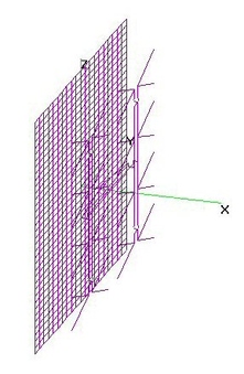
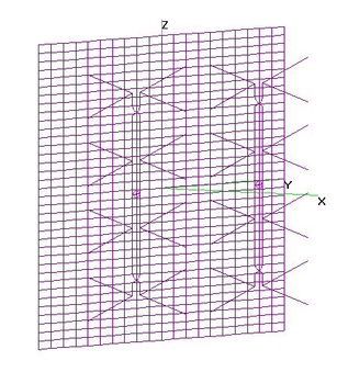
Old CM4228 (holl_ands) w Screen Refl (3 Dec 2011)Old CM4228 (holl_ands) with Screen Reflector analyzed using 4nec2.
Measurements derived from an Actual CM4228 I bought in 2008, importing Horizontal Harness
from Ken Nist's cm4228a.eznec file. Note small differences in some dimensions compared to Ken Nist's:
BowLength = 8.0-in, Bowtie Spacing = 8.0-in, Tine Separation = 5.25-in. Approx. AWG10 wire size (0.102" O.D.).
Feedline Separation = 1.3-in, with 0.7-in Hop at Crossover. AWG12 wire size (0.088" O.D.).
Center of Crossovers 2.1-in from Center of Outer Bowties. Left to Right Bay Separation = 20-in.
Screen Reflector (36"H x 40"W), AWG12, 1"H x 2"W Grid. Separation from Bowties = 4.6-in (varies 4.5-4.75-in).
UPDATE (3Dec2011): Added 4nec2 analysis if MOVE Horizontal Harness from between Screen Grid and Bowties
to new location IN FRONT of Bowties. Although SWR just above 470 MHz was slightly improved, Gain on 470 MHz
dropped by 1 dB with reduced F/B and F/R Ratios. So modification did NOT improve overall performance.
UPDATE (9Dec2011): Added 4nec2 analysis for Hi-VHF. Note that there are separate 4nec2 files for UHF
and Hi-VHF frequency bands.
A deep Gain Hole was found on Ch11 and SWR was EXCESSIVE across entire Hi-VHF Band.
EDIT (29Mar2013): Added ANOMALOUS plots versus Bowtie Tine Separation and Bowtie Forward Sweep,
which can frustrate finding an "Optimum" set of dimensions.
I believe that this is a 4nec2 Modeling anomaly, rather than inherent in old CM4228 design.
It's unlikely Whisker movements of under 0.25-in result in significant Gain changes.
EDIT (10Jun2014): Added Grid Size Effectiveness Charts for 0.5"Hx1"W, 1"Hx2"W, 2"Hx2"W, 3"Hx2"W and 4"Hx4"W.
Raw Gain was about the SAME, except (as expected) some loss with and about 1-2 dB LOSS for 4"Hx4"W.
Front/Back Ratio was much better with 1"Hx2"W than 0.5"Hx1"W and progressively lower for 2"Hx2"W, 3"Hx2"W and 4"Hx4"W.
Front/Rear Ratio was about the SAME with 1"Hx2"W and 0.5"Hx1"W and progressively lower for 2"Hx2"W, 3"Hx2"W and 4"Hx4"W.
[Errata: Fixed earlier error in F/B for 0.5"Hx1"W.]
EDIT (10Jun2014): Also added 3"Hx2"W Grid Size....which nicely fits in-between plots for 2"Hx2"W and 4"Hx4"W.
Plots for 1"Hx1"W and 2"Hx4"W are not included, since they were within a few tenths of a dB of 1"Hx2"W and 2"Hx2"W
respectively. The spacing of the HORIZONTAL wires primarily determine performance, since Vertical Wires have
only minimal effect on Horizontally Polarized signals. |
| 4742 Visits
61 Images
Shared Album | |
|
 | 7.
Old CM4228 with Hollands Horiz Harness (3 Jul 2014)Old CM4228 with Hollands Horizontal Harness (HHH) replacing the Original Harness analyzed using 4nec2.
Dimensions of HHH OPTIMIZED using nikiml's Python Control Scripts were the WIDTH of the Feedline (Gap)
and X-Axis SEPARATION from the Center of the Bowties, similar to 2x2 4-Bay (H4) as well as the
Vertically Stacked 4-Bay Antenna designs. Bowtie Tine Separation and Sweep were also Optimized.
When surveying the "terrain", I noticed that original CM4228a model (posted by Ken Nist on HDTVPrimer)
did NOT include the two 1.25-in Diameter Tubes which support the Bowtie/Feedline structures.
Since HHH could intersect or be influenced by the close proximity, I added Vertical Tubes to MY
CM4228 (8.0x8.0) model, which uses MY ACTUAL MEASUREMENTS. This significantly improved SWR and the
low frequency roll-off problem found in Ken Nist's model, as shown in Charts. To facilitate Apples-to-Apples
comparisons, I also reran the RF Combiner Mod version after adding the Vertical Tubes.
Two HHH versions were Optimized to determine the "best":
ALT#1 - HHH is In-between Bowties and Reflector, providing best UHF & Hi-VHF performance.
ALT#2 - HHH is In-front of Bowties, included here in case a user prefers that arrangement.
##################################################################
ALT#1 - Optimized Dimensions for HHH In-between Bowties and Reflector:
Tine Sep = 4.0-in, NO Sweep. Gap = 1.3-in (about 1.25-in) = Separation between Feedlines,
Xh = - 1.12-in = Separation between Feedlines and Center of Bowties. Diagonal Wire Lengths,
Harness to Feedline = 2.69-in (Top-Left & Bottom-Right) AND = 1.67-in (Bottom-Left & Top-Right).
Yinner = 11.71-in = Y-Axis Distance from Harness to INNER Bowtie Feedline (Top-Left & Bottom-Right).
Youter = 11.71-in = Y-Axis Distance from Harness to OUTER Bowtie Feedline (Bottom-Left & Top-Right).
Each HHH wire Length = 16.07-in + 2 x 0.715-in eyelets on ends = 17.5-in. TOTAL.
Whatever lengths is needed to get around obstacles near attachment screws are to be subtracted
from Harness Length along Y-Axis, maintaining 1.12-in Separation between Harness and Bowties.
UHF Raw Gain = 14.8 to 14.7 to 17.8 dBi, F/B & F/R Min = 21.9 dB and SWR (300-ohms) Under 2.1.
Hi-VHF Raw Gain = 5.0 to 10.4 dBi, Peaky on Ch9, Hi-VHF F/B & F/R Ratio Minimum = 10.3 dB
and SWR (300-ohms) under 5.1.
Still, these are significant improvements over the AS-SHIPPED CM4228 version.
Views with Reflector Removed are included to facilitate seeing the HHH.
##################################################################
ALT#2 - Optimized Dimensions for HHH In-Front of Bowties:
Optimum Tine Sep = 3.125-in, NO Sweep. Gap = 0.92-in (about 1.0-in) = Separation between Feedlines,
Xh = -2.21-in = Separation between Feedlines and Center of Bowties. Diagonal Wire Lengths,
Harness to Feedline = 3.18-in (Top-Left & Bottom-Right) AND = 4.19-in (Bottom-Left & Top-Right).
Yinner = 12.9-in (about 13.0-in) = Y-Axis Distance from Harness to INNER Bowtie Feedline (Top-Left & Bottom-Right).
Youter = 12.9-in (about 13.0-in) = Y-Axis Distance from Harness to OUTER Bowtie Feedline (Bottom-Left & Top-Right).
Each HHH wire Length = 20.27-in + 2 x 0.74-in eyelets on ends = 21.75-in. TOTAL.
Whatever lengths is needed to get around obstacles near attachment screws are to be subtracted
from Harness Length along Y-Axis, maintaining 2.21-in Separation between Harness and Bowties.
UHF Raw Gain = 13.5 to 17.0 dBi, F/B & F/R Min = 19.9 dB and SWR (300-ohms) Under 2.6.
Hi-VHF Raw Gain = 8.7 to 6.4 to 9.3 dBi, but 2.5 dB NULL on Ch9 could be a Problem
Hi-VHF F/B & F/R Ratio Minimum about 10 dB, Except for DIP on Ch9 and SWR (300-ohms) = 24.2 to 2.3 to 4.4.
Although significantly lower Gain than ALT#1, these are small improvements over AS-SHIPPED CM4228 version. |
| 4967 Visits
54 Images
Gallery Album | |
|
 | 8.
Old CM4228 (holl_ands) - RF Combiner Mod (30 Aug 2010)Old CM4228 (holl_ands) analyzed using 4nec2 simulation, assuming the Horizontal Interconnect Harness
is replace by a pair of Baluns (one to each 4-Bay) which are summed using an RF Combiner Module.
Measurements were obtained directly by holl_ands from an antenna purchased in 2005.
BowLength = 8.0-in, Bowtie Spacing = 8.0-in, Tine Separation = 5.25-in. Approx. AWG10 wire size (0.102" O.D.).
Feedline Separation = 1.3-in, with 0.7-in Hop at Crossover. AWG12 wire size (0.088" O.D.).
Center of Crossovers 2.1-in from Center of Outer Bowties. Left to Right Bay Separation = 20-in.
Screen Reflector (36"H x 40"W), AWG12, 1"H x 2"W Grid. Separation from Bowties = 4.6-in (varies 4.5-4.75-in).
UHF Raw Gain Climbs from 13.5 to 17.5 dBi. UHF SWR is Very Good, although rises to 3.7 on lowest Ch14.
Hi-VHF Raw Gain is Very Good (8.9 to 9.3 dBi), however SWR is Excessive except on Ch12 & 13.
NOTE: Charts do NOT include RF Combiner Loss, which is "typically" 0.5 to 1.5+ dB, see:
www.antennahacks.com [Back-To-Back Combiner Loss - divide by two.]
EDIT (29Mar2013): Added ANOMALOUS plots versus Bowtie Tine Separation and Bowtie Forward Sweep,
which can frustrate finding an "Optimum" set of dimensions.
I believe that this is a 4nec2 Modeling anomaly, rather than inherent in old CM4228 design.
It's unlikely Whisker movements of under 0.25-in result in significant Gain changes. |
| 3872 Visits
23 Images
Shared Album | |
|
 | 9.
Old CM4228 Enclosed Bowtie Mod (27 Nov 2013)UHF Channel Master (Old) CM4228 (as built per holl_ands measurements) with
Enclosed Bowtie Modification analyzed using 4nec2.
UHF Raw Gain on lowest channels improved about 2 dB at expense of a Gain Dip near 670 MHz.
UHF F/B & F/R Ratio was slightly degraded, but SWR was significantly improved.
Hi-VHF Raw Gain significantly improved over the unmodified CM4228, consistently pointing
FORWARD with an improved F/B & F/R Ratios, while SWR remained Excessive, which may
or may not be an issue in any given situation.
Python Script Optimization should be used to determine "best" Whisker Length and
Tine Separation and (why not) also vary the Y-Coord of the Enclosed Wire's mid-point
to explore Indented to Pointed (Outdented?) Bowtie shapes. Hopefully the Gain Dip
near 670 MHz can be eliminated and the Max Gain moved down to 698 MHz. Might
even want to try "Stagger Tuning" with only half of the Bowties Enclosed. |
| 2470 Visits
11 Images
Shared Album | |
|
 | 10.
CM4228a (Nist) 8-Bay with Reflector (17 Aug2009)Channel Master CM4228a 8-Bay Bowtie with Screen Reflector analyzed using 4nec2. Three versions were considered:
a) Ken Nist's CM4228a.ez.nec file, unmodified. [There are subtle differences wrt what I measured.]
b) Modified modeling approach, replacing "Balun" with a simple SOURCE wire at the central feedpoint.
c) Moved Horizontal Harness from between the 5-Bay stacks from between Screen Reflector and Bowties to IN FRONT of Bowties.
BowLength = 7.87-in, Bowtie Spacing = 8.0-in, Tine Separation = 5.5-in. Approx. AWG8-9 wire size (0.125" O.D.).
Feedline Separation = 1.25-in, with 1.25-in Hop at Crossover. Approx. AWG8-9 wire size (0.125" O.D.).
Center of Crossovers 4.8-in from Center of Outer Bowties. Left to Right Bay Separation = 20-in.
Screen Reflector (36"H x 40"W), AWG12, 1"H x 2"W Grid. Separation from Bowties = 4.5-in.
On the lower UHF channels, Raw Gain falls off and SWR is much higher, resulting in poor Net Gain.
This illustrates the need to rescale to a larger size antenna.
Hi-VHF Raw Gain in the FORWARD direction is moderate, except for notches at 180 MHz (between Ch7 & Ch8) and 205 MHz (Ch12).
Note that on these channels, Raw Gain is improved in the REVERSE direction. SWR on Ch7 & Ch8 is also excessive,
which could cause standing wave problems.
UPDATE (3 Dec 2011): Ken Nist's cm4228a.ez model mimics a Balun coming directly FORWARD from the feedpoint.
This results in worst case SWR of 3.9. Since the Balun might be going backwards, or downwards, I eliminated it.
SOURCE wire is directly across feedpoint, mimicing Balun wires with minimal length.
Worst case SWR improved from 3.9 to 3.3, which is a fairly minor improvement.
UPDATE (3 Dec 2011): Analysis if Horizontal Harness is MOVED from between Screen Reflector and Bowties and to IN FRONT of Bowties.
Worst case SWR improved from about 3.3 to about 2.8 and Gain was barely affected, with only few tenths of a dB loss on 470 MHz.
Hence this modification is barely worth the effort. |
| 6716 Visits
45 Images
Shared Album | |
|
 | 11.
CM-4228a (Nist) If RF Combiner Mod (27 Mar 2010)Old CM-4228 8-Bay Bowtie analyzed with 4nec2 with an RF Combiner Mod replacing the original Feedline between left & right bays.
Ken Nist's CM4228a.ez.nec file was modified, replacing the Feedline with a simple SOURCE wire at the center feedpoint on each 4-Bay stack.
This required the use of TWO "EX Cards" vice the usual one EX. For SWR & Impedance measurements, one of the EX Cards must be disabled.
There is very little Net Gain difference up thru Ch51, considering AT LEAST an additional 0.5 dB loss in a typical RF Combiner, although the
RF Combiner Mod does provide 1 to 3 dB higher Raw Gain on the lowest channels and 1-3 dB more on the highest.
Even better performance should be expected when applied to larger, Super-Sized 8-Bay antennas as the Max Gain moves to a lower frequency.
If one of the Baluns is REVERSED, a DUAL BEAM pattern results, with each beam about 2.4-2.8 dB lower than a single beam and a NULL in between.
NOTE: Charts do NOT include RF Combiner Loss, which is "typically" 0.5 to 1.5+ dB, see:
www.antennahacks.com [Back-To-Back Combiner Loss - divide by two.] |
| 5203 Visits
22 Images
Shared Album | |
|
 | 12.
A-C U8000 8-Bay - 9 Split RR AltHarness (18 May 2013)Antennacraft U-8000 8-Bay Bowtie with 9 Split Reflector Rods analyzed using 4nec2.
Dimensions from a 4nec2 file posted by 300ohm in April 2011.
More accurate Harness model. |
| 4580 Visits
20 Images
Shared Album | |
|
 | 13.
A-C U8000 8-Bay - 9 Full-Width Refl Rods (18 May 2013)Antennacraft U-8000 8-Bay Bowtie, modified for 9 FULL-WIDTH Reflector Rods analyzed using 4nec2
(eliminated 1/4-in Gap between each Pair of Reflector Rods).
Modification reduced F/B & F/R Ratios.
Dimensions from a 4nec2 file posted by 300ohm in April 2011. |
| 8550 Visits
20 Images
Gallery Album | |
| |