1
BSA civilian contract, approx 1930's no1 mk3, 'Regulated by Fulton'.
| 
2
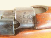
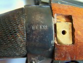
Many Fulton's rifle are marked 'Regulated by Fulton', in this case its simply marked 'G Fulton'.
| 
3
9651 is the rifles original serial number, 505C appears to be the Fulton's number. This is the only place it appears.
| 
4
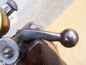
Matching bolt but not nosecap or barrel.
|
5
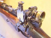
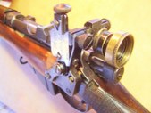
The Rolls Royce of enfield aperture sights; AJP (Parker Hale) Model TZ, or 'twin zero' sight, with Parker Hale iris/6 filter combination unit, also equipped with 1.25 inch large filter or lens holder.
| 
6
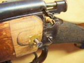
Stock repair where wood had been removed for the large square Central No4 sight mounting plate.
Wrist checkering is 'flat top diamonds', a stock British military style, but probably added by a subsequent owner, not by Fultons. Not suitable for service rifle matches but OK for open competition.
| 
7
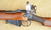
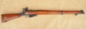
Rifle is a 1930's civilian contract rifle by BSA.
A split fore end has been reinforced with a through bolt and a threaded brass plate on the receiving end, repairs in process.
| 
8
Right side BSA civilian contract approx 1930's no1mk3, 'Regulated by Fulton', H barrel equipped, marked with MA and Lithgow stars but undated..
|
9
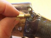
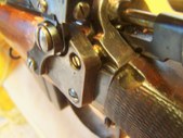
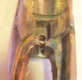
The receiver's inner safety bearing has been threaded. The post in hand was shaped from a brass bolt.
Most likely this was to provide a much more secure anchor for the aperture sight. I've taken this one step further and threaded the upper end for an anchor nut to pull down on the sight mounting plate as well, its going nowhere under recoil.
| 
10
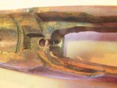
Brass post in place where the safety once was, anchored with loctite. The inner end had to be slightly shaped to permit smooth movement of the bolt in the channel.
Through bolt for stock repair/reinforce is partially seated. Wood repair from a badly fitted Central sight almost finished.
| 
11
A nice fit around the wrist, with no room for the safety mechanism, a step halfway along the post stops the plate from folding inwards.
| 
12
Aperture sight is a 1930's Model TZ or Twin Zero by Parker, eyepiece is an iris with 6 hole/filter unit. The larger brass unit is a 1.25 inch filter or lens holder.
|
13
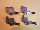
4 Parker Hale PH5a sight mount plates, all except the lower right show evidence of being reshaped to fit the rifle they once attached to.
If you're fitting aperture sights to your enfield try your best to mount the plate accurately, with spacers if needed, before contemplating cutting into the wooden stock.
| 
14
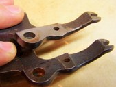
PH5a mount plates, upper is modified to fit a rifle, the lower one is in near new manufactured shape. The U shaped hump in the middle is a factory supplied high spot to help the sight mount clear of the fore end. This ends up being reshaped by gunsmiths and others.
| 
15
There's some bedding material where the receiver rests, and some also evident in the magazine well to broaden the rail where the receiver rests.
The fore end sides around the lower portion of the knox have been widened away from the metal, except for a 1/2 inch bearing surface left and right of the screw post, and the main bearing in the barrel channel.
| 
16
A different angle to emphasize the patches where the receiver presses down.
The trigger screw bushing is in place and of stock dimension.
|
17
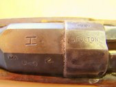
H or heavy profile barrel, MA marked on the left side, and Lithgow stars on the right side, no date, an aftermarket addition by some unknown shooter, post ww2.
| 
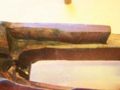
18
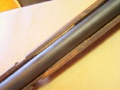
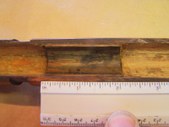
Mid barrel bearing, situated just aft of the barrel band, bearing appears to consist of a hard wood block with a square base inserted into a hollow in the fore end and glued in place, with the upper shaped to fit the barrel.
Note that the barrel channel clears the barrel sides by at least 1/8th inch for the full length of the barrel.
| 
19
The mid barrel bearing, 2 inches long, about 1/2 inch behind the barrel band, and in this case about 1/16th inch proud of the barrel channel. A thin paper will not pass between the barrel and the bearing due to downwards pressure.
This downward pressure remains if the barrel front is raised to its shooting position in the nosecap.
| 
20
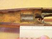
Rear bearing, appears to be a hardwood block glued into a recess, 1 inch long and shaped for the barrel, 3/4 wide approx, sits slightly proud of the surrounding wood.
|
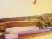
21
Previously installed and now removed bearing mid way between knox and the barrel band. Consists of a square block epoxied into the barrel channel, grooved through for the barrel.
Obviously tried and not enjoyed.
| 
22
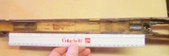
A reference for lengths between the bearings.
| 
23
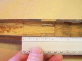
A few traces of epoxy or similar bedding material shows the action is/was bedded to the receiver.
Fore end has been widened at the forward end to accommodate the metal addition to the receiver.
| 
24
Slight traces of bedding material along the sides of the magazine well and towards the knox area.
Fore end wall has been widened in the forward area to accommodate the metal additions on the receiver.
|