1
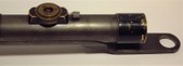
Right hand view of a vintage 3 power WW1 1915 dated Aldis pattern No 2 sniper scope "recycled" into use for WW11 for the Alexander Martin sniper rifle set up.
| 
2
Right hand view of the rear eye end of scope showing the classic Aldis stepped Brass housing containing eye lenses. Also shows the rear bracket that was affixed to rifle, this was adjustable for lateral movement.
| 
3
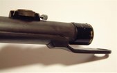
Right hand view showing the range drum assembly, the Objective Glass (OG) housing and the front mounting bracket.
| 
4
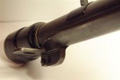
This view shows you that the scope tube was soldered into a piece of cut steel pipe and the front and rear brackets welded on to the steel pipe. It is possible that screws were used to initialy fix and try fitment that may be hidden by scope body and or welds?
|

5
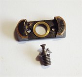
A close up view of the rear fixing bracket also showing the slotted "stop" grub screw protruding through from opposite side.
| 
6
Another view of the left hand side of the rear bracket.
| 
7
A view of the underneath of rear bracket showing the elongated slot allowing an arc movement for lateral adjustment when retaining screw fitted.
| 
8
A right hand view of the front bracket that affixes to front base, note it is pretty parallel to the scope body.
|

9
A view underneath of front bracket showing cranked step and dressed welded construction.
| 
10
Another canted left hand side view of bracket. It was noticed on this particular scope and others seen that here was a noticeable sideways twist in the bracket, probably purposely introduced during construction to collimate scope to rifle bore and ensure reticle pointer and horizon wire were upright in relation to rifle receiver. If not otherwise they would have had to unsolder scope body from tube again and rotate as required? That would have required scope innards to be removed again, so was twisting the bracket the easier remedy?
| 
11
A top view of the Range Dial and saddle assembly. Originally being a pattern 2 type Aldis this scope would have had a saddle with a lower wall height than the later pattern 3 and 4 scopes and this it retains. Also the Patterns 1 and 2's originally had only a single non-adjustable zeroing range dial. Later pattern 3 and 4 scopes had a higher saddle to account for a 2 piece range dial disc that could be adjusted for zeroing by unscrewing 3 grub screws and rotating top engraved dial to desired range setting, 1 - 6 Hundred yards being the normal markings. Instead of retro fitting the range assembly from a Pattern 3 or 4 scope, parts appear to have been borrowed from the spares held of Watts telescopic sight Range dial parts to achieve the same sort of adjustment as the pattern 3 and 4 scopes would give.
| 
12
Another view facing toward rear of the back bracket assembly.
|

13
Another view of rear bracket directly looking at from undeneath.
| 
14
Yet another view at different angle of rear bracket.
| 
15
As 14 aside.
| 
16
A full length view of scope and bracket assembly from underneath.
|

17
A view of the legend Alex Martin Gunmaker Glasgow stamped into front bracket. At first this double stamping concerned me as to being original, but others have been seen same. Perhaps they had the apprentice on the job and he was on the 'pop' the night before? Maybe Peter Laidler would care to comment by comparing with the examples held in School of Infantry Warminster?
| 
18
Same view but closer as picture 8.
| 
19
A downards view of the rear ocular lens housing bearing the legend Aldis Brothers Birmingham No 67500 1915. The finish appears to have originally been a stove enameled black paint possibly also varnished to protect.
| 
20
A view of the scope tube still showing the old SMLE rifle number O 648 beautifully hand engraved into tube. This scope shows signs of having been originally a James Purdey & Sons fitment to SMLE from the old soldered ring marks present and engraving type.
|

21
A view of disassembled scope,the observant will note that the erector cell lenses housing is missing, this is still in the tube.
| 
22
as 21 aside.
| 
23
A close up of the components of the range dial assembly.
| 
24
Another view of range dial parts but reversed view of parts.
|
25
A view of the range saddle and the range elevating screw.
| |